


Prototyping Rotor Blades Using 5‑Axis CNC: Expert Techniques
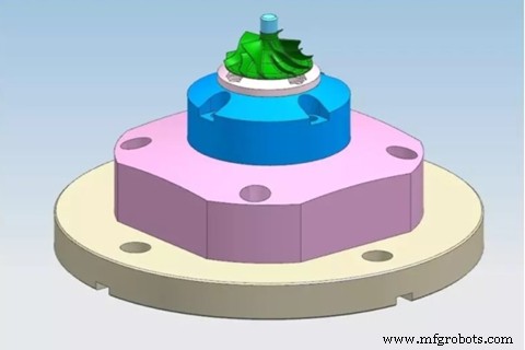
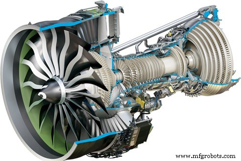
Posted on Oct. 8th, 2019, | By Victoria, WayKen Project Manager In ordinary life, most of us don’t know what’s rotor and how to make one. However, to a fanatical engineer, that’s the only item in his brain. Firstly let’s learn about what is the rotor. Rotors or rotor blades, a fan in the engine of a car or airplane, improves the performance of the engine by blowing fuel vapor into the engine using exhaust gases. A rotor is a rotary power machine that converts the energy of a flowing medium into mechanical work. It is one of the main components of aero engines, gas turbines and steam turbines. To a manic engineer, all he wants is a rotor blades prototype with high precision, which makes his design work well. How to perfectly make rotors or rotor blades prototype by 5-axis CNC milling? Today, natural gas combustion is the second largest power generation in the world. Natural gas is converted into electrical energy by a gas turbine, and the rotor of its compressor is a major difficult component encountered in the manufacturing process. The development of turbine blades is from the initial solid blade to the hollow blade, from the machining of the residual blade to the non-remaining blade, then to the oriented (single crystal) hollow blade. The tectonic evolution of modern turbine blades is evident, and the shape and lumen of the blades are becoming more complex. Milling is a machining process in which a rotary cutting tool is used to remove material. Fields of application for milling freeform surfaces are, for example, mold making and the aerospace industry. In addition, turbine blades and impellers are complicated parts that are machined by milling tools. To use 5 axes machining the rotor blade, the bottom flat surface of the rotor part is set up and the inner hole is centered, then the main work is to machine the blade shape. Here’s the traditional processing method of turbine fixture: The cylinder pushes the lever arm to be pressed from the top of the part. Such a scheme has obvious defects. The creative fixture uses a pneumatic action mode, which is spring self-locking mode, no need to connect the air source after clamping, the clamping force is about 400kg. After setting up the fixture, it’s time to start machining the blade shape by 5-Axis CNC. This improved solution has three advantages. In order to allow complete and uniform processing of the blades, it is necessary to create an auxiliary surface for each side of the blade and extend it in u and v directions. These auxiliary surfaces are used as drive surfaces for generating tool paths. Overall, the surface quality obtained was satisfactory and never exceeded 1 μm Ra. Comparing the blade roughness between them, it can only be said that the roughness of the second blade is lower than the roughness of the fourth blade. Before starting the other side of the blade, the first blade of three machining stages (roughing, semi-finishing and finishing) is carried out on one side of the blade, followed by good surface finishing (mainly in the first side being machined) there is still material in the adjacent space between the blades. However, there are still gouging marks on the surface, and the possible origin is the tool path generated by the CAM system. When machining the other side of the blade, due to the lack of rigidity of the elongated geometry being machined, noise is heard, there are signs of chattering at the top of the blade, and burrs are left. In order to avoid these problems, it is necessary to mill aluminum thin walls (like turbine blades) and alternately mill the side channels of the blades in steps of 0.5 to 2 times the milling diameter. The policies used by the third and fourth blade servers follow this recommendation. The processing of the third blade is divided into two stages, and the processing of the fourth blade is divided into three stages, and once the length of the elongated feature is reduced, higher rigidity is expected. However, there are chatter marks and burrs on the top of these blades. Splitting the blade only reduces the noise level and the number of burrs, but in terms of roughness, it cannot be said that there is an improvement. For the second blade with the lowest roughness value, this strategy does not consider recommendations for at least the roughing stage prior to finishing operations. Due to the lack of accessibility and privilege of privilege, the operation is divided into four stages, with the blade sides alternated. Both adjacent spaces of the eighth and last blade are roughened and semi-finished before the operation is completed. The tool then mills the inserts to the same contour, so the step size is 0.5 to 2 times the diameter of the milling, as recommended by pre-machining and milling of thin walls with alternating blade sides. After deburring and sanding smooth carefully, it needs to do bead blasting to obtain an attractive surface. We use CMM combining with 3D scanners to inspect all the dimensions of the rotor to ensure the high precision of +/-0.005″ which is as per the requirement of the customer. We are proud of our team doing such amazing work which obtains high recognition and praise from customers. Rotor blades are key components of aero engines. It is a typical difficult-to-machine workpiece. In fact, it may also be the “external display” with the highest appearance rate. Many companies often use this workpiece as a description of their processing capabilities, so excellent rotor blades processing solutions also represent strong corporate strength. As a professional one-stop prototype provider, WayKen is capable to machine rotor part with complicated structures by 5-axis CNC milling. If you need more CNC machining or CNC aluminum services, please contact us at info@waykenrm.com, you deserve better prototypes.
The Background of Rotor
Traditional processing fixture solution
Accurate fixture solution
Processing and Inspection of the Rotor
Concluding Remarks
CNC Machine
- CNC vs. 3D Printing: Choosing the Right Production Method
- Master 5-Axis CNC Machining: Comprehensive Guide & Industry Benefits
- How to Build Superior Metal Prototypes: Proven Methods & Best Practices
- Upgrade Your Workshop: Transition from 3-Axis to 5-Axis CNC Machining for Superior Precision
- 5-Axis CNC Machining: Unlocking Precision, Efficiency, and Design Freedom
- Choosing the Best Method for Aluminum Prototyping: A Practical Guide
- Expert Guide to Creating High-Quality Plastic Prototypes
- Cut CNC Prototype Costs: 3 Proven Strategies for Designers
- Elevate Production Efficiency with Advanced 5-Axis CNC Milling Solutions
- Master 5‑Axis CNC Machining: Expert Guide for Precision Manufacturing