



Essential GD&T Machining Symbols Every CNC Engineer Must Know
CNC metalworking is a precision craft that demands rigorous quality control. Even a fraction of an inch can turn a functional assembly into a failure. To guarantee consistency, engineers rely on a standardized language of geometric dimensioning and tolerancing (GD&T).
What Is GD&T?
GD&T is the industry‑standard framework for defining and communicating tolerances, form, orientation, and location of features on a drawing. Rather than writing lengthy specifications, a single symbol conveys a complete tolerance. The system uses 14 foundational symbols, organized into three primary categories: form, orientation, and location.
Categories of GD&T Symbols
1. Form Tolerances
Form symbols control the overall shape of a feature, refining size limits and ensuring uniformity across a part.
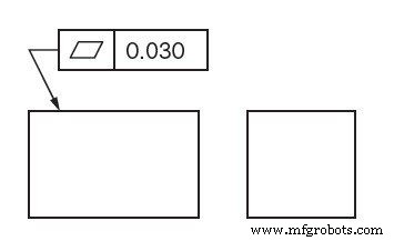
Flatness
Flatness specifies how level a surface must be, independent of any datum or reference feature. It is critical when a part requires a uniformly flat surface.
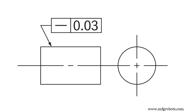
Straightness
Straightness limits the deviation of a line or surface from a true straight line in two dimensions. It is often applied to flat surfaces such as the face of a block.
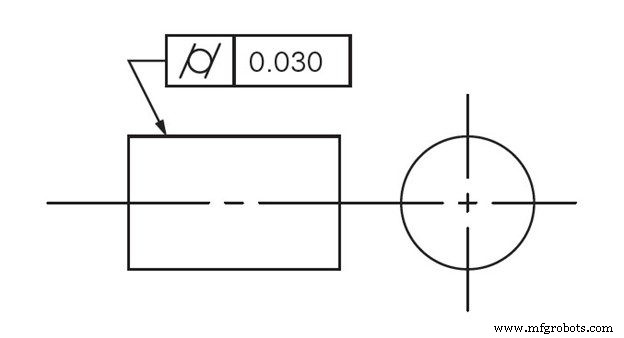
Cylindricity
Cylindricity measures how closely a feature conforms to a true cylinder. Two concentric cylinders—inner and outer—define the tolerance zone along the entire length of the part.
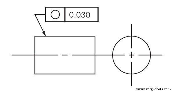
Circularity (Roundness)
Circularity describes how a cross‑section fits within a true circle. Unlike cylindricity, it applies only to a 2‑D plane.
2. Orientation Tolerances
Orientation symbols control the tilt of a feature relative to a datum. They are usually applied alongside basic angle dimensions and can also influence form when used on surfaces.
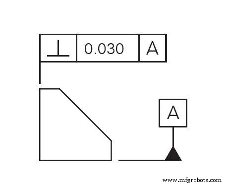
Perpendicularity
Perpendicularity ensures a referenced surface or line is at a 90° angle to the datum surface or line.
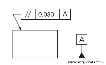
Parallelism
Parallelism demands that a feature run parallel to a datum surface or line throughout its entire length.
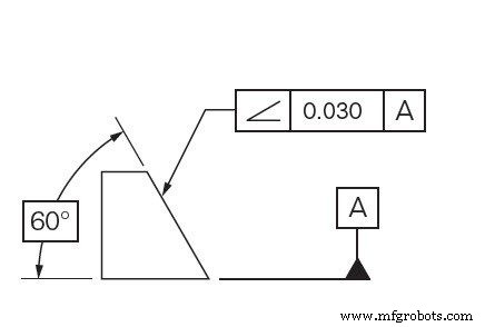
Angularity
Angularity specifies a precise angular relationship between a feature and a datum, beyond the 90° constraint of perpendicularity.
3. Location Tolerances
Location symbols govern the exact placement of a feature. They are paired with basic linear dimensions and can control position, profile, and overall geometry.
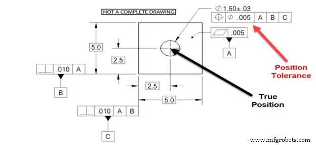
Position
Position, or true position, locates the median plane or axis of a feature. It can be applied regardless of feature size or under material condition, making it one of the most versatile GD&T symbols.
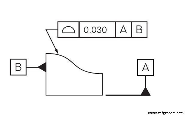
Profile of a Surface
This symbol defines a 3‑D tolerance zone around a surface—usually a curve or shape—ensuring every point on the surface falls within the zone.
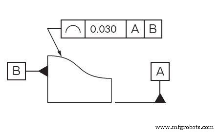
Profile of a Line
Profile of a line creates a 2‑D tolerance zone around a linear feature, allowing controlled variation in cross‑section for curved or irregular shapes.
Precision Machining and Delivery from Winndeavor
In metalworking, precision is non‑negotiable. Parts must fit perfectly within their designated spaces, which is why meticulous design and execution are essential. GD&T provides a universal language that saves time, reduces errors, and ensures high‑quality outcomes.
Winndeavor is dedicated to delivering precision components on schedule. Learn how we integrate GD&T and advanced CNC technology to meet your exact specifications by visiting our website or contacting our team.
Related Articles
CNC Machine
- The Evolution of CNC Machinery: From 18th Century to Modern Precision Manufacturing
- A Timeline of Heidenhain CNC Control Innovations
- Tool Retract & Recover: CNC Dictionary Definition
- Top CNC Machine Types: A Comprehensive Overview
- Crafting a Precision Model Clock with a CNC Router for My Daughter
- Optimizing CNC Workholding for Precise Milling Operations
- Malaysia’s 7 Best Laser Engraving Machine Suppliers for Reliability & Quality
- Understanding Laser Cutting Machines: How They Work
- Essential Wearable Components in a Fiber Laser Cutting Machine
- Top Affordable Metals for Precision CNC Machining