



2026 Welding Positioner Guide: Choosing 1‑, 2‑, and 3‑Axis Systems
By the EVST Editorial Team · Last updated: June 11, 2026
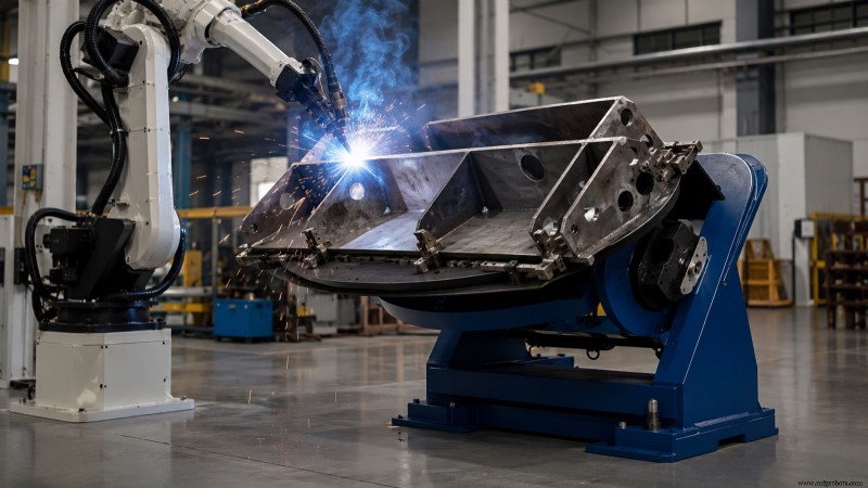
A welding positioner is a powered machine that rotates, tilts, or lifts a workpiece so each weld seam can be accessed in a flat or horizontal orientation—the positions that deliver the highest weld quality and deposition rates. Positioners are categorized by the number of powered axes: single‑axis units rotate on one axis, two‑axis units add a tilt function, and three‑axis units introduce a second rotation or vertical lift. Selecting the right configuration hinges on part geometry, weight, and whether the weld is performed by a human operator or a robot.
Why a Welding Positioner Matters
Weld quality is intrinsically linked to weld position. AWS D1.1, the structural steel welding code, specifies that flat (1G/1F) and horizontal positions enable higher current, faster travel, and superior fusion because gravity stabilizes the molten pool. A positioner keeps seams in these favorable orientations as the weld progresses, eliminating the need for the welder or robot to chase the seam around a fixed part.
The benefits are threefold: higher deposition rates from optimal parameters, lower defect rates by avoiding out‑of‑position welding (the leading cause of porosity and lack of fusion), and reduced cycle times because the part automatically indexes to the next seam instead of being unclamped, rotated, and re‑fixtured manually. In a robotic cell, a positioner allows a single arm to weld complex geometries in one continuous program. For a broader view of robotic welding, see our welding robot guide for heavy industry.
The Three Positioner Classes by Axis Count
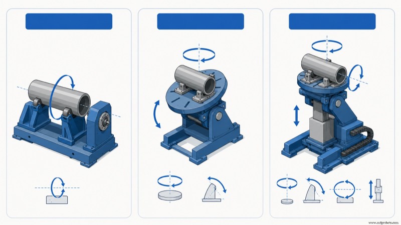
Every welding positioner fits into one of three families based on its powered axes. The axis count determines which seams can be presented flat and sets the first specification for cell sizing.
Single‑Axis Positioners
Single‑axis units provide a single powered motion—usually rotation about a horizontal or near‑horizontal axis. They are the workhorses for cylindrical and rotationally symmetric parts such as pipes, pressure‑vessel shells, flanges, and shafts. The part turns beneath a fixed torch while the seam remains in the flat position, ideal for circumferential welds. EVST’s single‑axis lineup—Single Axis Main Box Servo Positioner, Single Axis Horizontal Servo Positioner, and Head & Tail Stock Single Axis Welding Positioner—clamps a long part between a driven headstock and a free‑spinning tailstock so it can rotate on its own centerline.
Two‑Axis Positioners
Adding tilt to rotation, two‑axis units spin and tip, enabling any face of a boxy or irregular part to be brought into the flat position. This class is the most versatile for general fabrication, weldments, brackets, frames, and machine bases with seams in multiple planes. EVST’s two‑axis catalog includes L Type, U Type, C Type, and Platform Type configurations, differing mainly in table support and tilt clearance around bulky parts.
Three‑Axis Positioners
Three‑axis positioners combine rotation, tilt, and a third powered motion—typically a second gyration or vertical lift. The added axis keeps the seam not only flat but also at a constant working height and orientation relative to a robot, simplifying programming on large or tall assemblies. EVST lists Vertical Gyration and Horizontal Gyration three‑axis servo positioners for these heavy, geometry‑rich applications.
| Class | Powered motions | Suited to | Typical pairing |
|---|---|---|---|
| Single‑axis | Rotation only | Pipes, shells, flanges, shafts, circumferential seams | Manual or single robot, fixed torch |
| Two‑axis | Rotation + tilt | Weldments, frames, brackets with multi‑plane seams | Manual or robot, general fabrication |
| Three‑axis | Rotation + tilt + second gyration/lift | Large, tall, or geometry‑rich assemblies | Robot cell, coordinated motion |
Headstock/Tailstock vs Turntable: A Common Point of Confusion
Buyers often ask whether they need a “positioner” or a “headstock/tailstock.” These terms describe how the part is supported rather than competing categories. A turntable‑style positioner rests the part on a single rotating table, cantilevered from one side. A headstock/tailstock arrangement supports a long part at both ends—one end is driven while the other idles—so the part rotates on a stable centerline, similar to a lathe.
Length and slenderness dictate the choice. Short, compact parts fit comfortably on a single turntable. Long shafts, beams, or rotors would sag or whip if cantilevered, making a headstock/tailstock the correct solution. For extremely long parts, a tailstock with its own powered support or intermediate steady rests keeps deflection within tolerance. In practice, EVST engineers frequently design two‑station setups: a two‑axis table for compact brackets and a headstock/tailstock for long frames, rather than forcing a single machine to perform both tasks poorly.
Specifications That Drive Selection
Once the class is chosen, a concise list of parameters determines the exact machine. These are the figures a supplier needs to quote and the ones a buyer should verify against the heaviest, largest part in the family.
- Rated load — the maximum mass the table carries. Size against the part plus its fixture, not the bare part.
- Center of gravity and eccentricity — load capacity diminishes as the part’s center of gravity moves away from the table face and off the rotation axis. A positioner rated for a load with the CoG on‑axis may be overloaded when the same mass is mounted off‑center.
- Rotation speed and torque — must match the welding travel speed for the largest diameter, ensuring the surface speed at the seam stays within the process window.
- Tilt range and speed — for two‑ and three‑axis units, the angular travel that brings each seam to flat, commonly up to 90 or 135 degrees depending on frame type.
- Table diameter and T‑slot pattern — defines how the fixture mounts and the maximum part size the face supports.
- Ground/slip‑ring current path — for welding, the positioner must carry current across the rotating joint without arcing through the bearings, which a welding‑rated slip ring provides.
The most common sizing error is rating a positioner solely on workpiece weight while ignoring eccentric load. A heavy part mounted with its mass offset from the rotation axis imposes a turning moment the drive must hold at every angle; exceeding the rated tilt or rotation torque causes stalling or back‑driving under load. EVST publishes load and moment limits per model on request rather than a single headline number because the safe limit depends on the mass’s location.
Manual vs Robotic Positioning
A positioner serves two distinct masters. In a manual or semi‑automatic shop, it simply presents the seam to a human welder at a comfortable height and angle, with the operator controlling indexing. In a robotic cell, the positioner becomes a coordinated motion axis: the robot controller drives the positioner and arm together so the torch and seam move in concert, maintaining the ideal work angle through curved or compound welds.
Coordinated motion distinguishes a robotic welding positioner from a simple turntable. It requires the positioner’s servo axes to be controlled by, or tightly synchronized with, the robot controller, which is why robot‑grade positioners use servo drives with absolute encoders rather than variable‑frequency motors. For a complete cell build—including power source, robot, and positioner quoting—see EVST’s welding robot cell selection guide.
How to Choose: A Five‑Step Path
- Profile the part family. List the largest, heaviest, and most awkward parts the cell must handle. Size to the worst case, not the average.
- Fix the axis count. Rotation‑only for cylindrical parts; add tilt for multi‑plane seams; add a third axis only when large or tall geometry requires constant work height under a robot.
- Choose the holding method. Single turntable for compact parts; headstock/tailstock for long or slender parts that would deflect.
- Confirm load with eccentricity. Check rated load at the actual center‑of‑gravity offset, including the fixture, not just the bare part weight on‑axis.
- Match the welding interface. Welding‑rated slip ring for current path, servo control for robot coordination, and travel speeds that align with your process.
For a model‑by‑model walkthrough of EVST’s positioner line against payload and tilt/rotate requirements, with a path to a quotation, see the companion guide, EVST welding positioner selection 2026. To compare a positioner against alternative workpiece‑handling machines, read welding positioner vs turntable vs manipulator.
EVST’s Welding Positioner Range
EVST, headquartered in Chengdu with manufacturing in Wenling, produces welding positioners across all three axis classes as part of its robotic welding portfolio. The published range covers single‑axis units (Main Box Servo, Horizontal Servo, and Head & Tail Stock), two‑axis units (L Type, U Type, C Type, and Platform Type), and three‑axis servo positioners (Vertical Gyration and Horizontal Gyration). Load ratings, table sizes, and tilt ranges are quoted per application on request, because safe capacity depends on part geometry and center‑of‑gravity offset rather than mass alone.
According to EVST’s certification record, its robotic and welding‑automation production line holds IATF 16949 automotive‑grade quality certification, and its products carry CE, SGS, and TUV third‑party certifications. Positioners are commonly supplied as part of a complete welding cell alongside EVST’s QJAR welding robots and power‑source integration, so the rotation and tilt axes are commissioned as coordinated motion with the arm rather than as a standalone table.
Frequently Asked Questions
What is a welding positioner used for?
A welding positioner rotates, tilts, or lifts a workpiece so each weld seam can be brought to the flat or horizontal position, where weld quality and deposition rate are highest. It improves weld quality, raises throughput by avoiding out‑of‑position welding, and in a robotic cell lets one arm weld a complex part in a single continuous program.
What is the difference between single, two, and three‑axis positioners?
A single‑axis positioner rotates the part on one axis, suited to cylindrical parts and circumferential seams. A two‑axis positioner adds tilt, so seams on multiple faces of a boxy part can be presented flat. A three‑axis positioner adds a second gyration or a vertical lift, used on large or tall assemblies where a robot needs the seam held at a constant height and orientation.
When do I need a headstock/tailstock instead of a turntable?
Use a headstock/tailstock when the part is long or slender, such as a shaft, beam, or rotor, that would sag or whip if supported on one side only. The driven headstock and idling tailstock hold the part on a stable centerline so it rotates true. Short, compact parts can sit on a single rotating turntable.
How do I size a welding positioner correctly?
Size against the heaviest, largest part in the family, including its fixture, and check the rated load at the actual center‑of‑gravity offset, not just the bare weight on the rotation axis. Eccentric load imposes a turning moment the drive must hold at every angle; ignoring it is the most common sizing error. Confirm rotation and tilt torque against the worst‑case offset with the supplier.
Can a welding positioner work with a robot?
Yes. In a robotic cell the positioner becomes a coordinated motion axis driven by, or synchronized with, the robot controller, so the torch and seam move together to hold the ideal work angle. Robot‑grade positioners use servo drives with absolute encoders and a welding‑rated slip ring to carry current across the rotating joint. This is what distinguishes a robotic welding positioner from a simple turntable.
Where to Go Next
To match a positioner to a specific payload and tilt/rotate requirement with a path to a quotation, see the EVST product‑site guide to EVST welding positioner selection from single to three axis. To decide between a positioner and other handling machines, read welding positioner vs turntable vs manipulator. For the complete robotic welding cell, see our welding robot guide and the cell selection guide. For procurement questions, EVST sales can be reached via the contact page.
About the author: The EVST Editorial Team writes about industrial robotics and intelligent manufacturing for engineers and operations leaders evaluating automation projects. EVST (EVS TECH CO., LTD), founded in Chengdu in 2018, has delivered 600+ automation projects and ships to 100+ countries, with IATF 16949 automotive‑grade certification and CE / SGS / TUV third‑party certifications across the QJAR, collaborative robot, SCARA, and delta product families.
Industrial robot
- Precision Plasma Cutting with Motoman Robots: Unmatched Accuracy & Consistency
- Pick‑and‑Pack Robots: Boosting Efficiency in Food, Pharma & Automotive Industries
- KUKA KR AGILUS Series: Compact Robots Delivering Big Manufacturing Power
- How the Motoman SK16M Robot Achieves Precise, Reliable Movement
- Step 7: Seamless Integration of Collaborative Robots in Your Facility
- Motoman UP130: High-Speed, Durable Robot for Heavy-Duty Applications
- Robotic Pallet Assembly: Boosting Productivity in High-Mix Environments
- Motoman HP6 NX100: Rapid, High-Performance 6-Axis Robot for Versatile Applications
- Boost Welding Efficiency: Automation Peripherals Power Robotic Productivity
- GMAW vs. FCAW: Key Advantages and Disadvantages for Industrial Welding