


Step-by-Step Guide: Wiring a 3‑Phase Non‑Simultaneous Water Heater Thermostat
Three Phase Non-Continues Unbalanced Dual Element Electric Water Heater Thermostat Wiring
In our today post, we will be showing three phase non-simultaneous and unbalanced electric water heater thermostats and dual heating elements wiring (480V and 400V AC) in electric water heater wiring and installation series.
We already know the difference between balance and unbalance (imbalance) three phase water heater wiring discussed in three phase simultaneous water heater wiring, so we will stick to the three phase non-continuous water heater wiring only.
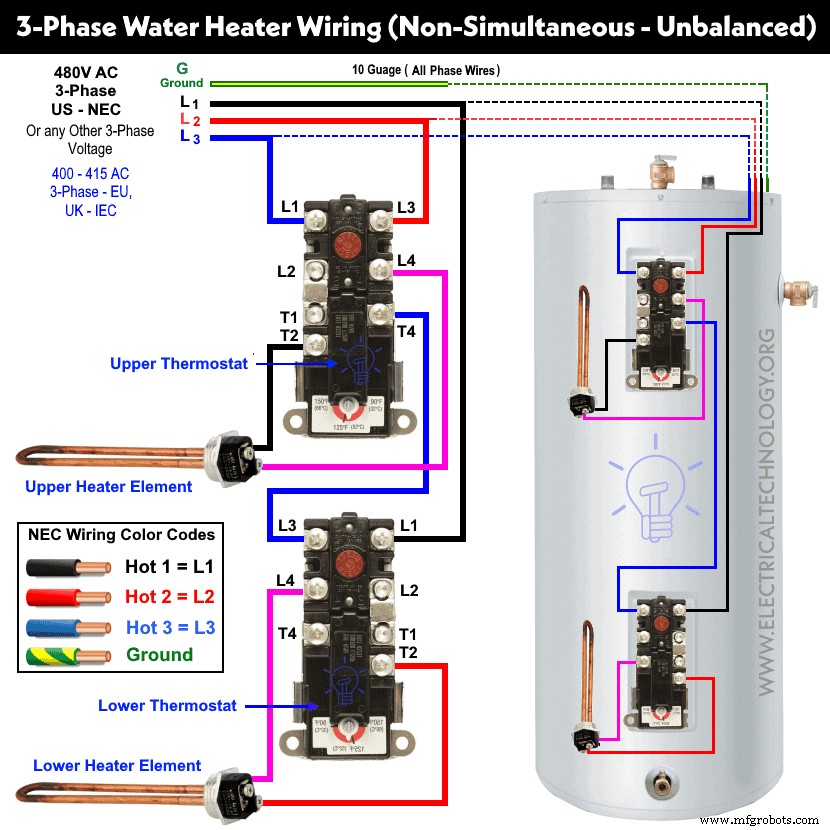
3-Phase Non-Simultaneous and Unbalanced Water Heater Thermostat Wiring
Non-simultaneous or non-continuous means that only one heating element and related thermostat operates at a time either lower or upper. In other words, the upper and lower thermostats and heating elements are wired in such a way where both are dependent on each other. When the upper heating element does its job, the wiring configuration automatically disconnects the upper thermostat as well as heating element and connects the lower thermostat and heating element.
Keep in mind that both the lower and upper thermostats are ECO-protected i.e. both are the same. In this wiring connection, the Line 1 (Black) is connected to the upper thermostat terminal L1 and latter L3 terminals of lower thermostat via terminal T4 of upper thermostat. Line 2 (Red) is connected to the L3 terminal of the upper thermostat and Line 3 (Blue) is directly connected to the L1 of lower thermostat.
Upper heating element is connected via T2 and T4 of the upper thermostat while the lower heating element is connected to the L4 and T2 terminals of the lower thermostat.
The same wiring diagram can be used for three phase 480V AC (US – NEC) or any other three phase supply like 3-Phase 400 – 415 V AC (UK & EU – IEC). Note that we have used red, black and blue for three phase hot lines for illustration purposes only. You may follow your regional electrical codes and wiring colors (see below section).
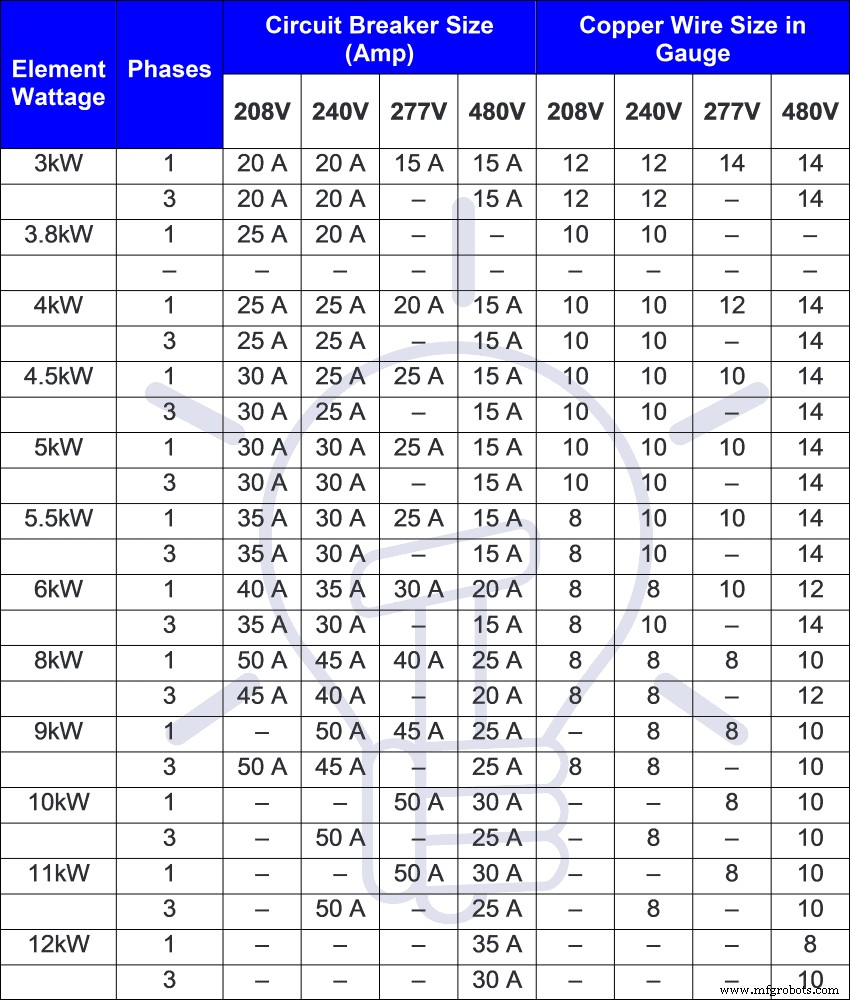
Circuit Breaker & Wire Size for 3-Phase Water Heater
A 6 gauge wire should be used for each line as this is non-simultaneous wiring (for simultaneous, we have used 6 gauge for each line). You may use the appropriate cable / wire and circuit breaker according to the heater rating. Check the user manual and nameplate data printed on thermostat and heating elements. The following table shows the suitable cable / wire size and fuse / circuit breaker protection size.
3-Phase Wiring Color Codes – IEC & NEC
You may use the local area codes instead of NEC or IEC wiring color codes when applicable to your region.
NEC:
120V, 208V & 240 AC (1 & 3-P):
Black = Phase 1 or Line 1, Red = Line 2, Blue = Line 3, White / Gray = Neutral and Green/Yellow = Ground Wire
277V & Three Phase 480V
Brown = Phase 1 or Line 1, Orange = Line 2, Yellow = Line 3, Gray = Neutral and Green or bare conductor = Ground Wire
IEC:
Three Phase 400 to 415V AC:
Brown = Phase 1 or Line 1, Black = Line 2, Gray = Line 3, Blue = Neutral and Green = Earth Conductor
General Precautions
Warning:
- Disconnect the power before replacing, repairing, troubleshooting, maintenance and installation electrical appliances and equipment.
- Use the suitable voltage and ampere rating of switch with appropriate wire size and proper size of breaker according to the load rating.
- Failure to do so can result in electrical shock, serious injury, fire or even death.
- Please follow the manual instruction, local area codes or contact a licensed electrician for proper installation.
- The author will not be liable for any losses, injuries, or damages from the display or use of this information or if you try any circuit in the wrong format. So please! Be careful because it’s all about electricity and electricity is too dangerous.
Related Water Heater Wiring Tutorials
- How to Wire a Single Element Water Heater and Thermostat?
- How to Wire 120V Water Heater Thermostat – Non-Simultaneous?
- How to Wire 120V Simultaneous Water Heater Thermostat?
- How to Wire 240V Water Heater Thermostat – Non-Continuous?
- How to Wire 240V Simultaneous Water Heater Thermostat?
- How to Wire 3-Phase Simultaneous Water Heater Thermostat?
- How to Wire 3-Phase Non-Simultaneous Water Heater Thermostat?
- How to Toggle Electric Water Heater Between 120V and 240V?
- How to Wire 120V & 240V Main Panel? Breaker Box Installation
- How to Determine the Number of Circuit Breakers in a Panel Board?
- How to Size a Load Center, Panelboards and Distribution Board?
- How to Determine the Right Size Capacity of a Subpanel?
- Single Phase Electrical Wiring Installation in Home – NEC & IEC
- Three Phase Electrical Wiring Installation in Home – NEC & IEC
- How to Wire Auto & Manual Changeover & Transfer Switch – (1 & 3 Phase)
- Even More Residential Wiring Installation Tutorials
Industrial Technology
- Step-by-Step Guide: Wiring a Three-Phase Simultaneous Water Heater Thermostat
- Step-by-Step Guide to Wiring a 240V Dual-Element Water Heater Thermostat
- Step‑by‑Step Guide: Wiring a 240V Dual‑Element Water Heater Thermostat (Non‑Continuous)
- Step-by-Step Guide to Wiring a 120V Simultaneous Water Heater Thermostat
- Step-by-Step Guide: Wiring a 120V Non-Continuous Dual-Element Water Heater Thermostat
- Step-by-Step Guide: Wiring a Single-Element Water Heater & Thermostat Safely
- Control Your Electric Water Heater with Switches: A Step‑by‑Step Guide
- Installing a GFCI Outlet: Step‑by‑Step Wiring Guide & Circuit Diagrams
- Step‑by‑Step Guide: Wiring an AFCI Combo Switch with Diagrams
- Step-by-Step Guide to Wiring a UK 3‑Pin BS1363 Socket Outlet Safely