


Measure Frequency with a Digital Multimeter – Step-by-Step Guide
Measurement of Frequency with a Digital Multimeter
Frequency is the number of cycles completed in one second of time. There are different kinds of multimeters that can measure frequency. Alternating current and other electrical signals possess frequency that affects the operation of a device. By using a multimeter, we can measure multiple quantities such as voltage, current, resistance, capacitance, frequency temperature and continuity, etc and testing electrical and electronic components such as resistors, capacitors, diodes, transistors and cables & wires etc.
In this article, we are going to study how a multimeter measures frequency and what are the factors that affect its reading.
Working Principle
A digital multimeter that can measure frequency has a peak-detection circuit. The meter measures the time between the two consecutive crests (peak of waveform) using the peak-detection circuit. it detects the peak of the input waveform and starts the timer. When the next peak of the waveform is detected, it stops the timer. The meter calculates the frequency using the time between the two crests of the waveform.
Measuring Frequency
Any digital multimeter that can measure frequency has “Hz” written anywhere on the dial and upon the ports where probes are inserted. It may also share a spot on the dial with “VAC” or “V~”.
There are two methods for measuring frequency on a multimeter. If your multimeter has a dedicated spot on the dial, then follow this method.
Method 1
- Turn the meter ON by switching the ON/OFF button.
- Turn the dial to “Hz”, it shares a spot on the dial with any other function such as “VAC or V~”. Pressing the “shift” button access the secondary option and starts measuring frequency. “Hz” appears on the display to confirm the meter has switched to frequency measurement.
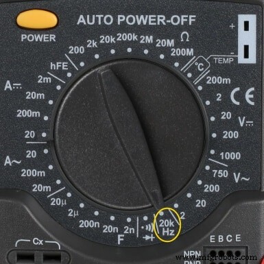
- Some multimeters have a dedicated spot for frequency measurement on the dial that has “Hz” written on it.
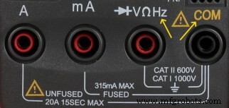
- Insert the black probe first into the “COM” port.
- Then insert the red probe into the port having “Hz” written on it.
- Connect the black lead first and then the red lead to the point of measurement.
- Note the reading from the display.
- If your multimeter has different ranges, reduce the range to get an accurate reading. Most multimeters have “auto range” button to select the proper range based on the reading.
- When finished, remove the red lead first and then the black lead.
- Remove the black and red lead from the meters ports.
- Turn off the meter or turn the dial to “voltage measurement” to avoid any potential damage in case of quick reuse.
Method 2:
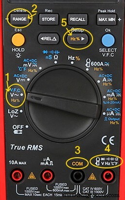
Some multimeters have a separate button for “Hz”. For such meters, follow the following procedure.
- Turn the meter ON by switching the ON/OFF button.
- Turn the dial to “VAC or V~”.
- Select the maximum voltage range, if the multimeter does not have an auto-range feature.
- Insert the black probe first into the “COM” port.
- Then insert the red probe into the port having “V Ω” or “Hz” written upon it.
- Connect the black lead first and then the red lead to the point of measurement. Swapping the leads does not affect the reading.
- Press the “Hz” button to switch to frequency measurement.
- Note the reading from the display.
- If possible reduce the range to get an accurate reading. Auto-range feature selects proper range based on the reading.
- When finished, remove the red lead first and then the black lead.
- Remove the black and red lead from the meters ports.
- Turn off the meter or turn the dial to “voltage measurement” to avoid any potential damage in case of quick reuse.
Problems Incurred during Frequency Measurement
There are many problems that can affect the frequency reading of a multimeter. We can reduce some of them to get an accurate reading.
Range of the Meter
The datasheet of a multimeter shows the lowest and highest frequency the meter can accurately measure. If the input frequency falls below the range, the multimeter may display a reading close to the actual reading but not accurate enough. The same thing will happen to a higher frequency above the range. The meters may not keep up with the actual frequency and display lower readings or show “OL” overload.
Therefore, it is necessary to know the range of the meter and the approximate frequency of the input signal.
Distortion in Input Signal
If the input signal has frequency distortion, it can affect the reading of the multimeter and cause uncertainty in the reading. The reading may also fluctuate. The signal can be filtered from noise by using a low pass filter.
Signal Radiation
Sometimes, the multimeter may pick up the frequency reading without probes touching the line. it may occur due to the unshielded lines that act as antennas to radiate the EMI (Electromagnetic interference). The meter picks up the signal, amplify and measure It and display the reading. It may or may not be accurate. Therefore, it is best to physically connect the probes to the wire.
Why do We Measure Frequency?
Measuring frequency is important because circuits and machines are designed to operate at specific frequencies. They either operate at fixed frequency or variable frequency where the output depends on it.
One such example is an AC electric motor whose speed is directly proportional to the frequency of the mains supply. A motor or transformer designed to operate at 50 Hz will run at a higher speed if connected to a 60 Hz supply. Similarly, a 60 Hz motor and transformer will be slower if it runs on a 50Hz supply. Here is an interesting question for you :) Is it Possible to Operate a 50Hz Transformer on 5Hz or 500Hz Frequency?.
Good to Know: Frequency can’t be measured using an Analog Multimeter. Only dedicated digital multimeters with specific features (like dedicated Auto Hz button or separate Com terminal) can be used to measure frequency in different ranges even up to 100kHz or more.
Industrial Technology
- Pro Guide: Testing NPN & PNP Transistors with Digital & Analog Multimeters – 4 Reliable Methods
- 8 Proven Methods to Test Capacitors with Digital & Analog Multimeters
- Master Multimeter Testing: A Step‑by‑Step Guide for Electrical & Electronics Components
- Step‑by‑Step Guide: Testing a Diode with Digital and Analog Multimeters (4 Proven Methods)
- Precise Power Measurement Using Digital and Analog Multimeters
- Accurate Resistance Measurement: Digital vs. Analog Multimeter Guide
- Accurate Voltage Measurement with Digital and Analog Multimeters – A Step-by-Step Guide
- Measuring AC and DC Current with Digital and Analog Multimeters: A Practical Guide
- Measuring Capacitance with a Digital Multimeter: A Practical Guide
- 6 Simple Techniques to Verify Capacitor Functionality