


Varicap Diodes Explained: A Comprehensive Guide for Electronics Professionals
Electronic circuits typically consist of resistors, capacitors, transformers, diodes, transistors, etc. Now, we will introduce a special diode type. Varicap diodes present useful applications in the electronics industry, providing voltage-controlled capacitance. Plus, they control voltage levels in a phase-locked loop.
These can integrate on all types of tuning circuits and frequency RF circuits. So let’s take a look! Understanding its purpose and the operational process can seem confusing. Therefore, we put together this guide to help you gain more knowledge on this particular subject.
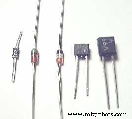
(Image showing a varicap diode. Source: Wikimedia Commons)
1. What is Varicap Diode?
A varied (variable capacitance) diode is a unique semiconductor, also known as a varactor or tuning diode. It provides voltage-dependent capacitance exploitation capabilities on the device’s p-n junction in reverse-bias.
2. Varicap Diode type and application
Below, we will discuss the different varicap diode types. We also explored some of the component’s applications.
Types
Hyper abrupt
Hyperabrupt varactor diodes provide higher capacitance for the voltage variation. It also operates with low voltage.
Abrupt
The most common type, abrupt varactor diodes, consists of a constant doping concentration. In this case, its junction undergoes a doping profile, controlled during the manufacturing process. Additionally, the capacitance stays inversely proportional to the voltage it receives.
Application
RF filters:
Actual varicap diodes can also provide filter tuning capabilities. This accordingly involves implementing tracking receivers in front-end circuits, allowing them to monitor incoming signals. Then, controlled voltage regulates this functionality through a digital to analog converter.
Voltage-controlled oscillators (VCO):
Various RF configurations include voltage-controlled oscillators with the varactor diode, a particularly crucial component. The oscillators’ primary operation notably involves phased locked loops. For this reason, these provide applications for frequency synthesizers or FM demodulators.
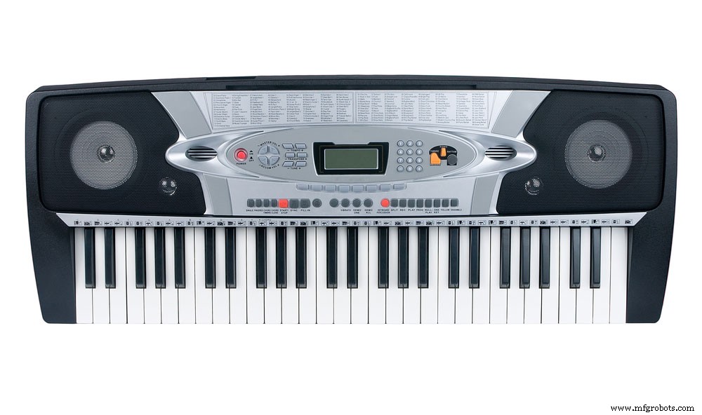
(Synthesizers contain a VCO, which utilizes a varicap diode)
Frequency and phase modulators also utilize varicap diodes. Frequency modulators usually integrate these across the electrical resonance in the generator, allowing the diode to receive audio. As a result, the capacitance will level with the audio. This triggers the frequency signal to move up and down, matching the capacitance variations under those circumstances.
In phase modulators, a varicap diode incorporates into the phase shift network, in which a frequency signal flows. The diode receives audio, causing the phase to sync with the audio variations.
3. Working principle of Varicap Diode
Varicap diode circuit diagram:
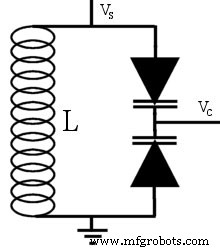
(Image showing a varicap diode on a circuit. Source: Wikimedia Commons)
Variable diode circuit symbol:
Looking at the variable diode’s schematic symbol below, you will see that it contains similar characteristics as a PN-junction diode. That’s because the varicap diode features an anode and a cathode terminal. You will find the diode positioned at one end of the symbol. Meanwhile, the opposing end contains two parallel lines to symbolize the capacitor’s conductive plates. Finally, the space between those two plates represents the insulating dielectric.
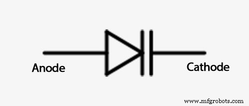
(Variable diode circuit symbol. Source: Wikimedia Commons)
Formula:
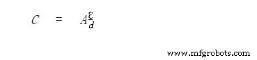
Three parameters affect the varicap diode’s capacitance. They include the PN junction’s cross-section (A), semiconductor’s (Ɛ), and the depletion region’s width (d). For instance, you will find this represented in the below formula:
Working principle:
We will need to look at a capacitor to understand the varicap diode’s working principle. Capacitors generally contain two conductive metal plates with an insulating dielectric placed between the two. A varicap diode’s P-type and N-type regions serve as the conductive plates, while the depletion region represents the dielectric. Due to its similar build and design as a capacitor, the diode produces capacitance.
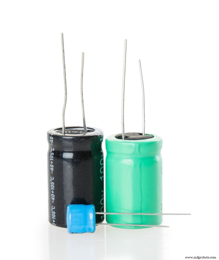
(A varicap diode contains similar features as a capacitor)
The capacitance increases if the dielectric constant boosts or both plates have a shorter distance between them. However, a greater distance between the two or declining dielectric constant results in decreased capacitance. At the same time, a varactor diode’s capacitance is proportional to the junction’s cross-sectional region. And it’s inversely proportional to the depletion region’s width. Thus, capacitance changes occur due to the depletion region’s width adjustment.
Hence, a varicap diode in reverse bias will consequently cause depletion region changes. For starters, the region will widen once the reverse bias increases. In effect, the space between the N-type and P-type grows, which reduces capacitance. Decreasing the reverse bias will cause the depletion region to tighten. As a result, the distance between both N-type and P-type regions will shorten, increasing capacitance. Therefore, applying different reverse bias voltage on the varicap diode changes the capacitance.
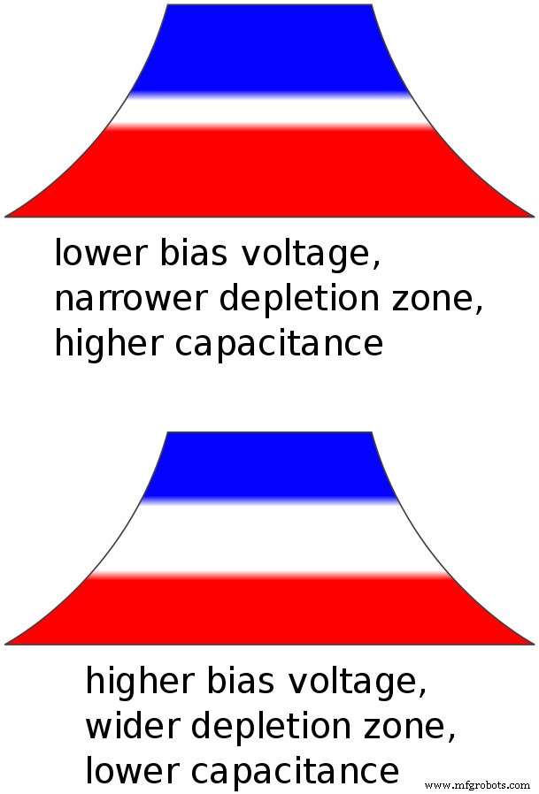
(Image demonstrating the effects of increased and decreased capacitance. Source: Wikimedia Commons)
Basic Operation:
The varicap diode essentially stores electric charge. In that case, these components generally function in reverse bias. Applying reverse bias voltage will cause the n-region electrons and p-region holes to separate from the device’s junction.
4. Varicap Diode equivalent circuit
A varicap diode usually contains several main components, which can help when designing a diode equivalent circuit.
The different stray elements include:
- Rs (V): This serves as the series resistance for the diode. It differs based on the voltage received.
- CJ (V): The aspect utilized here exhibits the variable junction capacitance. It also serves as the diode’s primary element.
- LP: Binding wires in the varicap diode causes the series capacitance to increase.
- CP: This represents the parasitic capacitance. Connecting wires in the diode will cause the parasitic capacitance to increase around its junction.
5. The temperature coefficient of the capacitor
You can calculate the varicap diode’s capacitance coefficient temperature with the below formula:

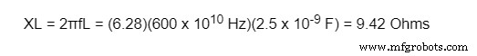
The ΔC value represents the device’s capacitance changes due to temperature variations (T1 – T0) during reverse bias. For example, we will look at a value where C0 equates to 29 pF with a VR of 3V and T0 at 25. Then, we calculate the varicap diode’s capacitance changes. With the VR value, the TCC will vary. As a result, the maximum frequency sets to 600MHz. You can then calculate the varicap diode’s reactance with the formula:
Conclusion
As we already know, varicap diodes serve as a useful component on electronic and RF circuits. Additionally, this device contains similar features as a capacitor, demonstrating how it increases or decreases the capacitance through a variance of reverse bias voltage. We also took a look at some of its applications, including RF filters, VCOs, and frequency & phase modulators. Generally, two types of varactor diodes exist today, abrupt and hyper abrupt. Each one serves its unique purpose for capacitance.
Do you have any questions regarding a varicap diode? Feel free to contact us!
Industrial Technology
- Mastering 2021: Proven Marketing Strategies for Manufacturing Success
- Master Social Media for Manufacturers: Comprehensive eBook Guide
- Robotic Palletizers Explained: Boosting Efficiency and Control
- Master Maintenance Management: Boost Efficiency & Cut Costs
- Mastering 3D Printing Supports: A Comprehensive Guide to Quality & Efficiency
- Ultiboard: Comprehensive Beginner’s Guide to PCB Design
- Mastering LED Drivers: A Comprehensive Guide to Efficient Lighting
- Understanding Fuses: A Comprehensive Guide to Protecting Your Circuits
- Bluetooth Communication Protocols: A Comprehensive Beginner’s Guide
- Comprehensive Guide to CNC Machining: Techniques, Applications & Best Practices