


Diode Testing Made Easy: Proven Techniques to Spot Faulty Components
If you’re an engineer or electronics designer, you know that almost every circuit features diodes. Indeed, they are one of the most common components in circuitry. And you can use them for several applications, including switching, protection, and other applications.
Despite how common and important they are, diodes are still electrical components and can get damaged. Interestingly, you usually can’t detect a faulty diode until it’s in your circuit.
Luckily, you can avoid such situations with a simple diode test. Read on to find out the different ways to test a diode.
Let’s start!
What is a Diode Test?
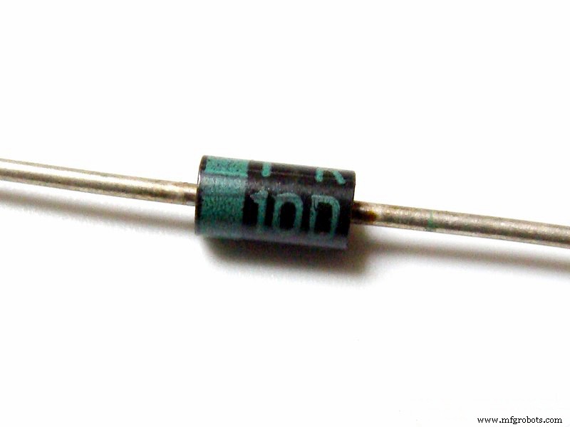
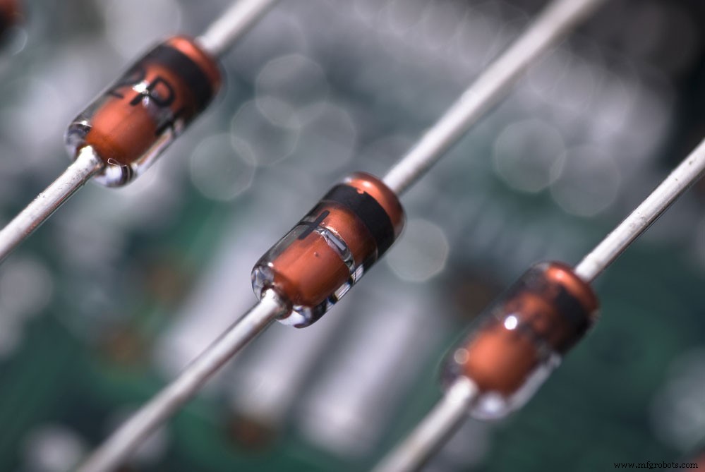
Diode
Diodes are small components that allow current to flow in one direction only. These little components are tricky and can get faulty at any time. Hence, the need for a diode test.
Simply put, diode tests are easy ways to check whether a diode is functioning. In addition, these simple tests can help you avoid circuit disasters.
So, we recommend testing your diodes before assembly. While you can test after assembly, detecting faulty components will be more challenging.
The most common way to test a diode is by using multimeters. However, there are other available methods used to get decent results and values.
Reasons for Diode Failure
There are several reasons why you can end up with a faulty diode. Common causes include unstable voltage regulation, open circuits, and short circuits. Moreover, there will always be signs when your diode has any of these problems.
These signs include a rising power supply voltage, unbalanced output, or supply voltage dropping to zero. Hence, you must thoroughly analyze a problem before doing your diode tests.
How to Test a Diode in a Circuit Board
As mentioned earlier, a multimeter is the standard tool for testing diodes. It can run on-board (diode on the circuit) and off-board measurements. Also, diode tests use a pretty basic principle for measurement.
According to the principle, you can measure the forward resistance and reverse resistance of the PN junction. Then, you can make your basic judgment based on the values you get from the measurement.
So, a good diode test requires understanding a diode’s basic working principle and structure. Also, you must understand the main reasons for diode failure.
Additionally, you can use an analog or a digital multimeter to test diodes.
How to Test a Diode using an Analog Multimeter
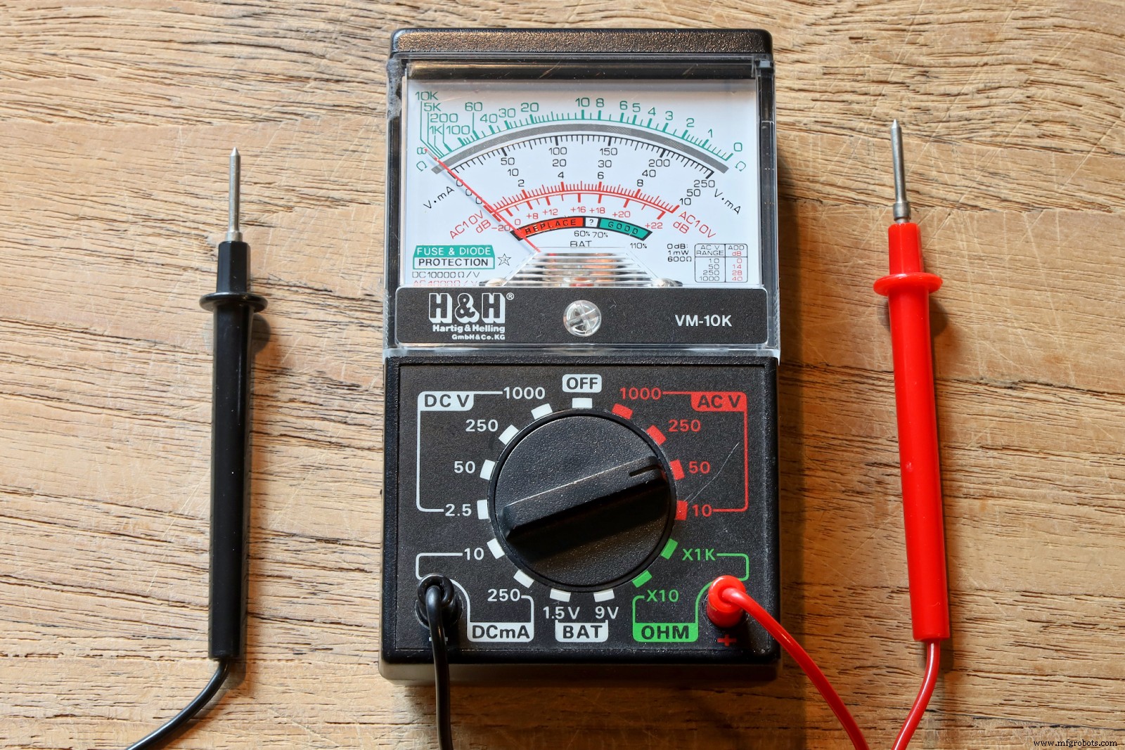
Analog Multimeters
Analog multimeters don’t have a special mode for testing diodes. But, you can use the resistance mode as an alternative. Here’s how to test a simple PN diode:
- First, set your multimeter’s selector switch to a low resistance value.
- Then, connect the multimeter’s terminals to the diode. Note that the positive terminal connects to the anode and the negative terminal connects to the cathode. Hence, it sets your diode in a forward-biased condition.
- You should have a functioning diode if your meter has low resistance values.
- Next, reverse the terminal connections to put the diode in high resistance (reverse bias) mode.
- If you get OL readings or very high resistance values, your diode is in perfect condition.
- You’ll have a faulty diode if you don’t see any of the above readings.
Note: This method is for simple PN diodes, which may not work for other diodes, like the Zener diode and LED.
How to Test a Diode using a Digital Multimeter
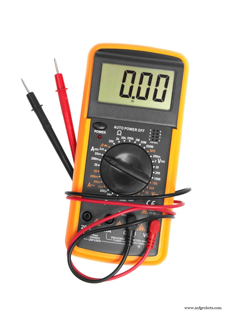
Digital Multimeter
You can use two modes to test your diode with a digital multimeter. These modes include turning your multimeter knob into diode mode and the ohmmeter mode.
Interestingly, the ohmmeter mode is the digital version of the analog multimeter’s resistance mode. Moreover, the diode mode is more effective as it relies on the diode’s characteristics.
How to test a Diode using Diode Mode
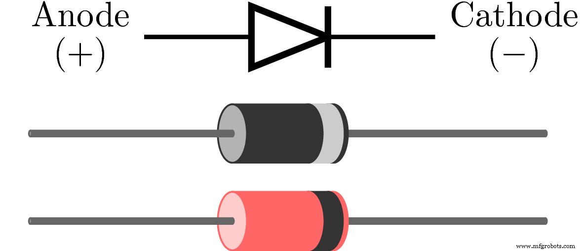
Anode and Cathode
For this mode, you’ll need to measure the voltage drop across the diode when it’s set in a forward bias state. If your diode is functional, it will allow current to flow in forwarding bias with a voltage drop.
Here’s how to do this test:
- First, identify the anode and cathode of your diode.
- Then, ensure your digital multimeter stays in diode checking mode. You can do this by adjusting the central knob towards the diode symbol.
- Once your multimer is in diode mode, it will supply approximately 2mA current to the diode.
- Next, connect your probes to the diode-under-test. The red probe connects to the anode, while the black probe connects to the anode. It will set the diode in a forward bias state.
- Check your multimeter’s readings. You should have a healthy silicon diode if it displays a voltage value between 0.6 to 0.7.
- The reading for a healthy Germanium diode is around 0.25 to 0.3.
- Finally, reverse your probe connections to set your diode in a reverse-biased condition. If it reads OL or 1, your diode is healthy.
Note: Anything other than those values means your diode is faulty.
How to Test Diode with Ohmmeter Mode

Ohm Symbol
- First, ensure your central knob points towards the ohm symbol. It would set your multimeter in ohmmeter mode.
- Then, set your diode in forward-bias condition. It’s the same connection as the diode mode test.
- If your readings show low values (tens of ohms), your diode is faulty. On the other hand, if it’s up a hundred ohms, then your diode is functional.
- Next, set your diode in a reverse-biased condition by reversing the probe connections.
- Your diode should have very high resistance or OL. Or you’ll have a faulty diode.
How to Test Zener Diode
Zener Diode
The Zener diode needs a different testing method because it naturally conducts in reverse-biased conditions. Here’s how to do this test:
- First off, use marks to identify your Zener diodes anode and cathode.
- Set your multimeter in voltage mode. Don’t forget to use the knob.
- Next, make your probe connections according to the diagram below.
- Now, slowly increase the input supply and watch the meter readings. You should notice that the output will also increase as the variable supply rises. It’ll stop once it reaches the breakdown voltage.
- At this point, you should see a value that won’t change even if you increase the input supply. If this happens, then your Zener diode is in good condition. If not, then it isn’t very accurate.
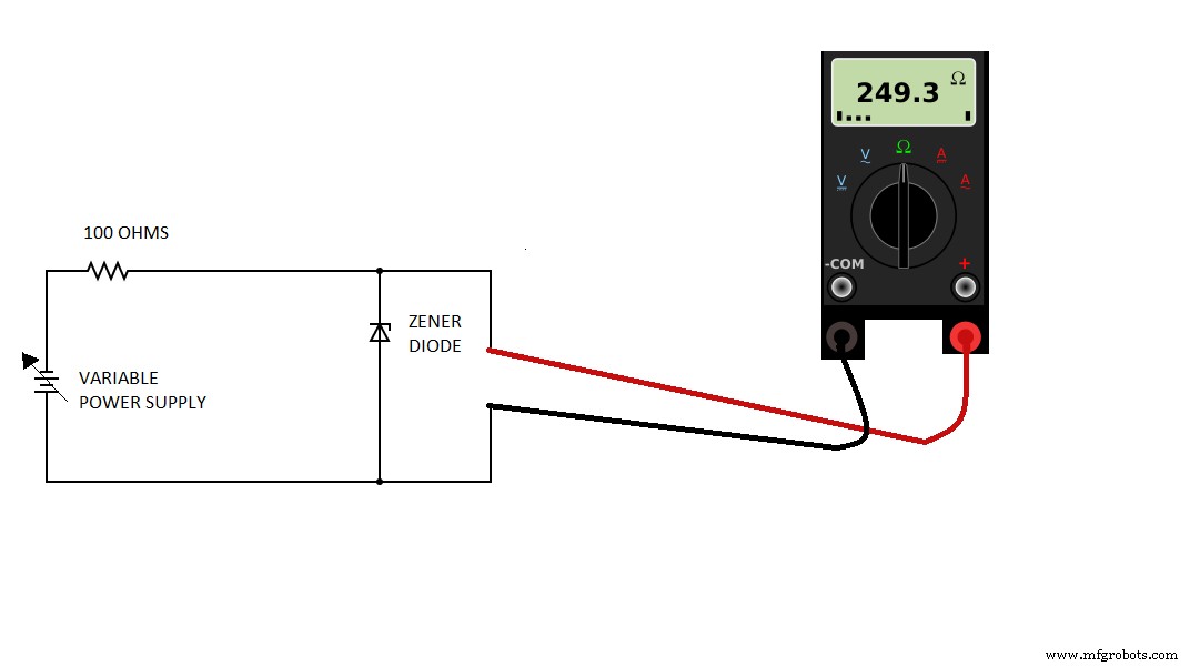
Circuit Diagram for Zener Diode
How to Test LED (Light Emitting Diode)
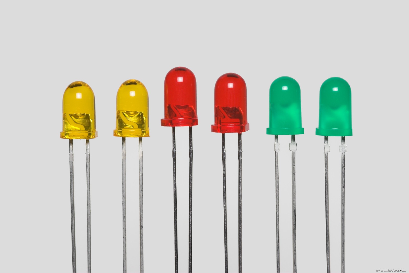
LEDs
The LED also differs from the regular diode and requires another testing method. Here’s how to get this done:
- First, identify your anode and your cathode. It’s easy to identify LED terminals. The long and positive terminal is the anode, while the short and negative terminal is the cathode.
- Then, set your multimeter knob on diode mode.
- Connect your probes so that your LED enters a forward-biased condition.
- Your LED will glow if it’s healthy or remains dark if it’s faulty.
- LEDs don’t work in reverse-biased conditions, so there’s no need for reverse-biased testing.
How to Test Diode without Multimeter
You can often spot a faulty diode by looking at it on the circuit board. For example, you should see some black scorch marks around the defective diode. But there are other ways to test your diode without a multimeter.
There’s the continuity circuit test and the component tester method. First, you’ll use some basic concepts to create a continuity circuit for the continuity circuit test. Then, place your diode in the testing area.
If your diode is healthy, it will complete the circuit and make the LED glow (forward-bias mode). However, the course won’t be complete for the reverse-bias method, and the LED won’t glow.
On the other hand, the component tester method requires you to insert your diode into the component test and check your readings. Your readings will show Vf if it’s healthy.
How to Test a Rectifier Diode
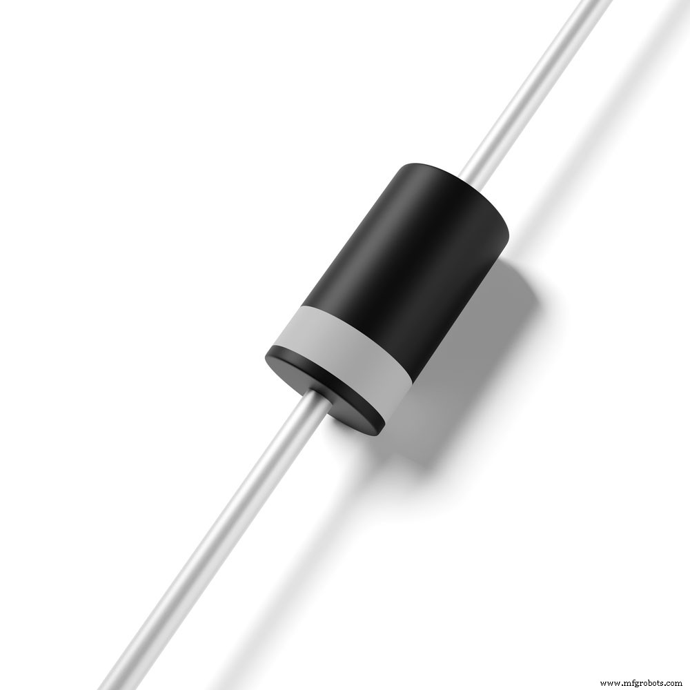
Rectifier Diode
Here’s how to test a rectifier diode with a digital multimeter:
- Set your multimeter’s knob to diode mode.
- Check if you’ll see an infinite voltage of three on your meter’s display.
- Next, connect your probes (similar to the other tests) to enter a forward-biased condition.
- Your display should show a minimum of 0.6v low forward voltage drop.
- Then, reverse your probe’s connections to enter reverse-bias mode. Your multimeter should show no readings—to pass the test.
Note: if your diode shows any values, you might have a leaky or defective diode. If it shows a 0000 reading, then your diode is shorted.
Multimeter Diode Test not Working
If none of the tests works, the problem might be from your multimeter. A faulty diode will show some reading on the multimeter. So, consider using a different multimeter for your diode test.
Rounding Up
Diodes are small and essential devices in any circuit. Hence, they can cause disasters when defective. Hence, you must always test your diodes before adding them to any course.
The multimeter is the most common tool to test your diodes. But, you can carry out diode tests even if you don’t have a multimeter. For example, you can use a component tester or continuity circuit test. Both methods are capable of showing you if a diode is healthy.
Be sure to contact us if you have any questions.
Industrial Technology
- Decode SMD Resistor Codes: Quick Guide to Determining Resistance Values
- Step‑by‑Step Guide: Testing a Diode with Digital and Analog Multimeters (4 Proven Methods)
- How Many Lights Can Fit on a Single Circuit Breaker? Expert Guide for 15A, 20A & 10A Circuits
- Determining the Number of Outlets per Circuit Breaker: A Practical Guide
- Choosing a Top-Quality VFD Drive Repair Service: A Practical Guide
- Choosing the Right Phenolic Bearing Supplier for Heavy Machinery: A Practical Guide
- PCB Manufacturing Process: Ensuring Superior Quality & Reliability
- Choosing the Right PCB Manufacturer: A Comprehensive Guide
- Choosing the Best Online PCB Manufacturer: A Guide to Top-Quality Service
- Testing a MOSFET: A Step‑by‑Step Guide to Accurate Performance Evaluation