


Streamline Sheet Metal Quoting: Accurate, Rapid, and Reliable Technical Data Solutions
Looking for a better way to quickly move your sheet metal quotes through our systems and, in the process, improve your designs? We can help. When it comes to getting a fabricated sheet metal part that is consistent with a complex set of technical requirements, ensuring that a supplier has all the necessary information to generate an accurate quote is the first (and most important) hurdle to cross.
Recently, most suppliers routinely required only a 2D drawing to translate geometry, material, surface finish, and other needs into a quote that provides a price and lead time. But the trade-offs with submitting only a 2D drawing were time and cost. It’s painstaking work to review technical details from a drawing and can only be accomplished by a person experienced in the art and science of sheet metal fabrication.
However, as technological advancements and proliferation of digital enabler capabilities assist people in doing the work of generating sheet metal quotes, the highly time-intensive process is shortening. There’s a flip side to this benefit: Technical requirements are now coming from different pieces of technical data, and in today’s world it is increasingly common to find suppliers asking for unique and different combinations of technical files to support various quoting processes:
- 3D CAD files may be analyzed for geometric attributes, locations of features, and potential issues, each of which can be compared to a set of manufacturing capabilities
- 2D drawings can remain an important way to communicate surface finish needs (for example, material grain direction), secondary operations such as hardware insert type and location, or geometry requirements that may not be easily communicated if a supplier prefers a neutral CAD file
- Additional supporting documentation can come in many forms. Silk screening a corporate logo may require that the artwork design be in vector format to ensure clear and crisp representation of the image, or a .DXF file could be a necessary part of understanding how to price a laser cut piece of flatwork
Naturally, this adds a layer of complexity to the product development processes for sheet metal, especially when time is of the essence during the initial stages of testing and validating designs.
This post offers some needed clarity about the technical information necessary to get a fast and accurate sheet metal quote from us.
Choosing the Right 3D CAD & File Types
As digitization of manufacturing processes continues to make the slow, but inevitable, evolution toward sheet metal fabrication, the importance of 3D CAD files for quoting and manufacturing applications will heighten.
Today, we require a 3D CAD file to generate and receive a quote. While we accept a variety of file types—the most common being .STEP, .STP, .SLDPRT, .x_t, and .IGS—it is typical for many uploaders to submit using the CAD platform neutral .STEP/.STP format. The rest of this post assumes you’re uploading a .STEP/.STP file.
The CAD file is important for several reasons:
- Immediately after upload, the CAD is analyzed so we can develop an understanding of the geometry requirements associated with the design. Our evaluation of the CAD file informs the scope of manufacturing processes needed to achieve the completed part during quoting. In short, the CAD file determines the route your physical parts will take through the factory.
- Identification of manufacturing issues can be complicated for any manufacturer and sheet metal fabrication is no different, in fact it may be more complex due to the number of disparate value-add processes. That said, we will routinely advise you when the following manufacturing issues are present:
- A feature is too close to another feature
- Bends are too close and may cause tooling interference
- You’re not using a Protolabs’ preferred internal bend radius
- Proximity of features and bends conflict with tooling/process requirements
- Part geometry is too large or too small for our process
- Exceeding minimum or maximum flange lengths (material and tooling dependent)
- If parts are ordered, the CAD file is a source of truth as the physical parts make their way through the factory. In-process checks are made against modeled dimensions to ensure features are located correctly and meet our prescribed tolerance outcomes.
While the 3D CAD model is critical for digital manufacturers to meet customer commitments, CAD models typically need additional technical information to fill in what the CAD file can’t communicate.
Adding Hardware Inserts to Models
Thanks to our long history of fabricating tens-of-thousands of unique sheet metal geometries, we know how important hardware inserts are to product designers. It’s common to require different types and counts on any given geometry, which is why we keep a running inventory of 2000 different inserts.
When it comes to communicating hardware insert requirements during the quoting process, we’ve seen all sorts of different methods and styles. The key question at hand is: Should hardware inserts be included in the 3D CAD file, or left up to a technical drawing to describe what is needed?
Our preferred design submission method is to include hardware in the 3D model. Specifically, the fastest and most accurate quotes are generated using the following approach:
- Include hardware inserts as solid bodies independent from the sheet metal component body, but packaged into a single 3D CAD file
- Modelling hardware into the design as a single body will slow the quoting and manufacturing process and may contribute to manufacturing delays
- Use common naming conventions from Penn Engineering—the primary insert OEM in the industry. Avoid internal naming conventions whenever possible or provide a key/legend for conversion to standard naming.
If modelling in hardware in this way isn’t an option, the best alternative is to submit a 2D drawing with hardware and thread type details. This path will take slightly longer to generate a quote, but our technical team will be able to process the information and provide an accurate quote.
The Value of 2D Drawings
It has been commonplace for sheet metal fabricators (and their customers) to rely on 2D drawings as the primary communication method for securing correct manufacturing requirements. Even with the advent of modern technologies designed to aid in delivering a quote faster than ever before, many fabrication businesses continue to use similar processes today. In these situations, highly skilled technical professionals or managers are responsible for reviewing and confirming feasibility of end-user requirements.
To get a sheet metal quote from us, 2D drawings are accepted as supplemental documentation to the required CAD file. However, it’s not always necessary to provide a 2D drawing if certain manufacturing processes or specifications aren’t in scope for the current stage of product development.
An important note regarding 2D drawings and our file upload process: Unless you’re selecting an eligible process, 2D drawings are not required. If you’re selecting from the eligible processes (welding, threaded holes, masked areas), you will be prompted to upload your technical drawing. It is possible to complete this component of the upload process either when you initially upload, or during quote configuration (after analysis). If you’re uploading during quote configuration, please note that as much as 24 hours is required to review the drawing.
Let’s dive a little deeper into what situations drive the need for a 2D file for quoting purposes, and what information we use to process:
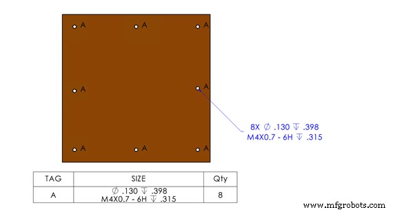
Threaded Holes
- Typical threaded hole annotations are recommended
- Callouts referencing threaded hole type (ex. M4) and count (ex. 4X) are acceptable
- Our library includes ANSI imperial or metric types and all options provide a 2B finish
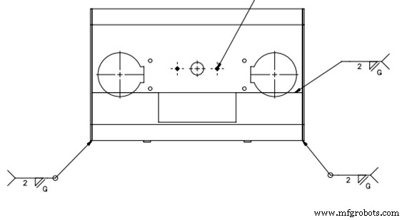
Welding
- Typical weld symbols and annotations are recommended
- Welding type and location information are critical
- We use MIG, TIG, and spot welding processes to achieve full seam, tack, and plug weldments
- Weld studs and nuts are OK to call out
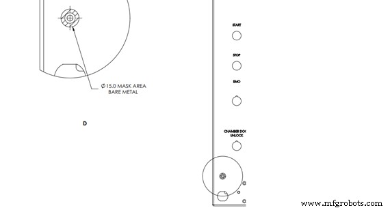
Masked Areas
- Typical masked area callouts and annotations are recommended
- Masking size and location information is critical
- Our standard rounds range from 0.313 in. (7.950mm) to 1 in. (25.4mm)
- Our standard tape ranges from 0.25 in. (6.35mm) to 2 in. (50.8mm)
Part Marking
- Typical annotations and call outs are recommended
- Our part-marking process is completed with ink in a stencil fashion. Note: We require part-marking information to be consistent from piece to piece, so requests such as serialization are currently not supported
- Critical part mark information is a visual representation of the alphanumerical layout and location; bag and tag is the standard output for our shipping process
- First Article Inspection: 2D drawings are required to complete AS9102 standard First Article Inspection forms
Other Documentation to Help Improve Your Quoting Experience
This section could be aptly re-named silkscreen documentation. Silkscreen documentation file type is less important than the image format. It is important to supply a vector-based image. The most common alternate image type is raster, like a photograph, but raster files are pixel-based and cannot be resized (especially enlarged) without image degradation.
Vector files, however, produce a high-quality digital image that can easily distinguish between one color and another regardless of size. Vector images are highly compatible with our silkscreen creation and application process. We typically see them used to highlight corporate logos and digital designs in a way that adds a professional appearance to the end product.
The bottom line is that if you have any questions regarding uploading or communicating technical data, contact one of our applications engineers by calling 877-479-3680.
Jamie White is sheet metal product manager and Scott Trecartin is a digital manufacturing designer at Protolabs.
Industrial Technology
- 5 Expert Tips for Precision Sheet Metal Design
- How CAD Models Drive Success in Metal Fabrication Projects
- Premium Hinges for Sheet Metal Enclosures – Precision, Durability, and Quick Delivery
- Expert Ventilation Solutions for Sheet Metal Enclosures
- Optimizing Enclosure Cooling: Perforated Sheet Metal for Efficient Ventilation
- Choosing the Right Hinges for Sheet Metal Enclosures
- Chemical Film Conversion Coating for Sheet Metal: Enhancing Durability & Performance
- Understanding Sheet Metal Gauge: Why Thickness Matters in Fabrication
- Expert Sheet Metal Design Tips for Precise Fabrication
- Choosing the Right Sheet Metal Fabrication Method for Your Project