


Mastering GDT for Precision Injection‑Molded Parts
The world of quality in the manufacturing industry is a big, complex place. From industry certifications to dimensional verification and process validation, there are tons of variables to consider. In most cases, these quality processes are critical to ensuring stability in each manufacturing process before moving on to produce components in higher volumes. Basically, it means measure twice, or 30 times in the case of a CpK, so you only have to cut once. But, as we know, a typical component can have many features, dimensions, and tolerances that might make or break part performance. In this blog, we’re going to address Geometric Dimensioning and Tolerancing (GD&T), a recent upgrade to our Critical-to-Quality (CTQ) process, and we’ll outline the various feature and dimensional measurement capabilities available, as well as the transparency that these features give our customers.
What is GD&T?
GD&T is an industry standard symbolic language used to communicate allowable geometric represents the evolution of the CTQ quality inspection process. When you submit a 3D CAD model, it gives us a strong indication of the specs for your part. GD&T takes it even further, providing us with specific features, such as position or flatness, that you would like us to measure. Specifically, you can provide us with the GD&T features listed below.
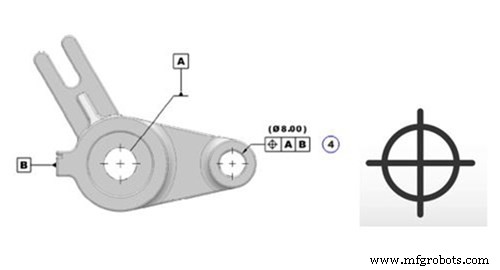
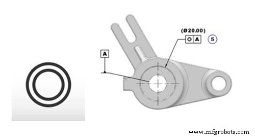
Position
In terms of the axis, point or plane, position defines how much variation a feature can have from a specified exact true location. The tolerance is a 2- or 3-dimensional tolerance zone that surrounds the true location where a feature must lie. This means that you will have an exact point where the position should be, and your tolerance specifies how far away the feature can be. This is usually called out as a diameter to represent a circular or cylindrical tolerance zone.
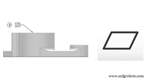
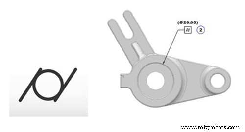
Flatness
This is a straightforward feature that measures how flat a surface is. It’s important to note that this symbol references flatness of a surface regardless of other features or datums that might exist on the part. Defined by two parallel planes, this feature is useful to call out on features that need to be uniformly flat without adjusting other dimensions on the drawing.
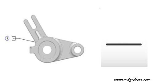
Straightness
Straightness can be defined as either surface straightness or derived median line (DML) straightness. Surface straightness is the standard form and is used to verify uniform straightness across a feature or surface. This is often applied to flat features but can also be applied to cylindrical features. In both cases, this feature is defined by the variance of a surface within a specific line.
DML straightness differs from surface straightness, in that it applies to the bend of the central axis of a part, usually a cylinder. In this case, DML becomes a 3-dimensional tolerance which defines how far the center axis of a part may bend or twist.
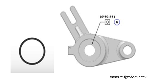
Circularity
Circularity, or roundness, defines the allowable variance between a circular feature and a true circle. This 2-dimensional tolerance defines the form of a circle, with the intent of verifying that the circle is not oblong, square, or otherwise out of round. Like flatness, circularity is measured independently from other features or datums.
Concentricity
Concentricity, or coaxiality, defines the central derived median points of a referenced feature to a datum axis. This feature is complex, because it relies on mathematically derived median points instead of the physical axis of a surface or feature.
Cylindricity
Cylindricity defines how close an object conforms to a true cylinder. This 3-dimensional tolerance defines roundness and straightness of the overall form of a cylindrical feature. Once again, this is measured independently of any other datum, and forms a cylindrical boundary around the object that the 3-dimensional feature must lie in.

Parallelism
Parallelism describes the orientation of one referenced feature to a datum surface or line. This commonly relates the orientation of one surface plane parallel to another datum plane in a 3-dimensional tolerance zone. This effectively means that the tolerance controls the angle between 2 features by controlling where the surface can lie.

Perpendicularity
There are two types of perpendicularity: surface and axis. It is defined by how close to 90 degrees a surface or line is from a datum surface or line. In general, surface perpendicularity is used to verify orientation of a one surface plane perpendicular to the datum plane. Axis perpendicularity can be referenced for a circular feature, and defines the cylindrical boundary where the axis of the referenced feature must be.

Profile of a Surface
Profile of a surface defines a 3-dimensional tolerance zone, usually in the form of an advanced curve or shape. Thus, when a profile measurement is called out on a curved surface, such as a fillet, the entire surface of the radius must fall within the tolerance zone. In this case, any variance inside or outside of the tolerance must fall within the surface profile tolerance.
As we referenced at the beginning of this blog, the addition of these GD&T features to our automated inspection capabilities provides an added layer of transparency to the quality control process. If you would like us to inspect any of the previously mentioned features on your next project, simply reference our inspection overview, contact our applications engineers, or speak with your account manager.
Industrial Technology
- Identifying and Managing Feature Gaps in SaaS Applications
- Plasma Arc Welding (PAW): Process Overview, Parts, and How It Works
- Gas Welding Explained: Process, Parts, and Applications
- Enhance Your Custom Enclosures: Mastering Type 2 & 3 Anodizing Techniques
- Evolution of CMMS: Past, Present, and Future – How Technology Drives Maintenance Success
- Maximize Efficiency: Inventory Management Software Features & Benefits
- Top 5 Design Strategies for Complex Injection-Molded Components
- Geometric Dimensioning & Tolerancing (GD&T): What It Is & Why It Matters
- Key Advantages of CNC Milling and Ideal Applications
- Expert Clear Plastic Injection-Molded Parts: Precision & Clarity