


Key Design Features of an AC Electric Arc Furnace for Efficient Steel Production
Design Features of an AC Electric Arc Furnace
Electric arc furnace (EAF) used for steel making apply high current and low voltage electric energy to the charge materials , and thereby melt and refine them. EAF is a batch furnace which consists of a refractory lined vessel covered with a retractable roof through which electrodes enter the furnace. General features of a typical AC electric arc furnace is shown in Fig 1.
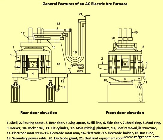
Fig 1 General features of an AC electric arc furnace
EAF has a large bowl shaped body with a dish shaped hearth. The shell has a refractory lining inside. The reaction chamber of the furnace is covered from above by a removable roof made of refractory bricks held by a roof ring. It is fed with a three phase alternating current (AC) and has three graphite electrodes which are connected by flexible cables and water cooled copper tubes.
The design of electric arc furnaces has changed considerably in recent years. Emphasis has been placed on making furnaces larger, increasing power input rates to the furnace and increasing the speed of furnace movements in order to minimize power off time in furnace operations.
Modern steel melting shops with EAFs usually employ a mezzanine furnace installation. In this type of installation, the furnace sits on an upper level above the shop floor. The furnace is supported on a platform which can take on several different configurations. In the half platform configuration, the electrode column support and roof lifting gantry is hinged to the tiltable platform during operation and tapping. When charging the furnace, the complete assembly is lifted and swiveled. This design allows for the shortest electrode arm configuration. In the full platform design, the electrode column support and roof lifting assembly is completely supported on the platform
The different components of EAF fall into the functional groups of (i) furnace structures for containment of the scrap and liquid steel, (ii) components which allow for movement of the furnace and its main structural pieces, (iii) components that support supply of electrical power to the EAF, and (iv) auxiliary process equipment which may reside on the furnace or around its periphery.
Furnace structures
EAF is cylindrical in shape. Its bottom consists of a spherically shaped bottom dish. The shell sitting on top of this is cylindrical and the furnace roof is a flattened sphere. The furnace bottom sits on a cradle arm which has a curved segment with geared teeth. This segment sits on a rail. As the tilt cylinder is extended, the furnace rocks forward for tapping the furnace. For removing slag from the furnace, the furnace is tilted backwards for which the tilt cylinder is contracted fully.
EAFs these days are of the split shell construction. In this construction, the upper portion of the furnace shell can be quickly decoupled and removed from the bottom. This greatly minimizes down time during the change out of the top shell. Once the top shell is removed, the furnace bottom can also be changed out fairly quickly.
The furnace sidewall above the slag line usually consists of water cooled panels. These panels are hung on a water cooled cage which supports them. Water cooled panels allow very large heat inputs to the furnace without damaging the furnace structure. Parameters which have a strong influence on panel life, include water quantity and quality, water flow rate and velocity, inlet water pressure and pressure drop across the panel, pipe/panel construction material, and pipe diameter. Water cooled panels are required to withstand high thermal and mechanical loads.
The furnace roof is either dome shaped or resembles a shallow cone section as is more common with water cooled roofs used in modern practice. The roof consists of a water cooled roof ring which forms the outer perimeter of the roof cage. This cage acts as part of the lifting structure for the roof. Water cooled panels are inserted into this cage and have a cylindrical opening at the centre. The refractory delta section is inserted to fill this opening. This delta section has minimum opening around the electrodes without risk of arcing between the electrodes and the water cooled panels. The whole furnace roof is cantilevered off the roof lift column. Typically, roof and electrode supports can be swiveled together or independently. The electrode stroke allows the electrodes to be swiveled with the roof resting on the furnace shell which allows for removal and replacement of the delta section without removing the roof. Generally, for a full platform design, a swiveling support with pivot bearing, bogie wheel and gantry arm is employed. For larger furnace, a roof lifting gantry is used.
The furnace bottom consists of a steel shell with several layers of refractories. The furnace bottom consists of a spherical plate section. This section is refractory lined with the lining normally consisting of a safety lining with a rammed working lining on top. In the furnaces, where gas stirring elements are installed in the bottom of the furnace, special pocket blocks are installed during installation of the brick safety lining. Alternatively, stirring elements are lowered into place and refractory is rammed around them. The furnace bottom section also contains the tapping mechanism.
Several openings are usually provided for furnace operations. The most obvious are the three electrode ports which allow the electrodes to go inside the furnace through the roof. In addition, a fourth hole is provided in the furnace roof to allow for extraction of the furnace fumes. A fifth hole may be provided for several reasons such as continuous DRI/HBI feed, coal injection or lime injection. These holes are at high up in the furnace and hence do not affect air infiltration into the furnace as much as lower openings. The lower openings in the furnace include the tap hole which is filled with sand and the slag door. The slag door was originally provided to allow decanting of the slag from the furnace. In modern furnaces, it is also used for providing access to the furnace for oxy-fuel burners and oxygen lances. Several ports are also usually provided around the circumference of the furnace shell for burners. Occasionally, an opening may be provided high up on the furnace sidewall to allow a water-cooled decarburization lance access to the furnace. Other openings may be provided low in the furnace sidewall or actually in the furnace hearth to allow for injection of inert gases, oxygen, lime or carbon.
Furnace movements
For EAF operations, it is necessary that several of the furnace components move. Typical requirements for movement include roof raise/rotation to allow for scrap charging, electrode raise/lower and swing to allow for scrap charging, electrode raise/lower for arc regulation, furnace tilt forwards for tapping, slag door up/down for deslagging operations, furnace tilt backwards for slag removal, electrode clamp/unclamp to adjust the working length of the electrode, and movement of any auxiliary systems such as the burner lance.
EAF is tilted both for tapping and for slag removal. During the furnace tapping, the maximum forward tilting angle is dependent on the type of furnace bottom. For conventional spout tapping, it is necessary to tilt to an angle of 45 deg to fully tap the furnace. For bottom tapping furnaces, the maximum tilt angle is usually 15 to 20 deg. An important requirement of slag free tapping is that the furnace can be tilted back quickly as soon as slag begins to carry over into the ladle. The typical maximum forward tilting speed is 1 deg per second and tilt back speed is 3 to 4 deg per second.
Normally furnace movements are made using a central hydraulic system which provides motive power. The hydraulic system consists of a central reservoir, filters, an accumulator, hydraulic valves and hydraulic piping. As hydraulic fluid passes through valves in one of two directions within a given circuit, hydraulic cylinders are extended or contracted to provide movement of various mechanical components. Without sufficient fluid flow and pressure within a circuit, movement is not possible. Thus issues such as low fluid level, low accumulator pressure, system leaks, fluid degradation due to overheating, solids build up in valves or in hydraulic lines and wear in mechanical components can lead to poor system performance and in some cases, system failure.
Furnace cooling water system
The cooling water system is important and integral to EAF operation. There are several cooling systems. Some operations, such as transformer cooling, delta closure cooling, bus tube cooling and electrode holder cooling, require extremely clean, high quality cooling water. These systems usually consist of a closed loop circuit, which conducts water through these sensitive pieces of equipment. The water in the closed loop circuit passes through a heat exchanger to remove heat. The circuit on the open loop side of the heat exchanger typically flows to a cooling tower for energy dissipation. Other water cooled elements, such as furnace side panels, roof panels, off gas system ducting, furnace cage etc. typically receive cooling water from a cooling tower.
The cooling circuit typically consists of supply pumps, return pumps, filters, cooling tower cells and flow monitoring instrumentation. Sensitive pieces of equipment normally have instrumentation installed for measuring and monitoring the cooling water flow rate and temperature. In case of water cooled equipment, interruption of the flow or inadequate water quantities can lead to severe thermal over loading and in some cases catastrophic failure.
Lubrication system
Normally EAF has automatic lubrication system which provides lubrication to different moving parts based on various operations occurring during making of a heat. For example, some parts are lubricated every three roof swings, following tapping. Some components such as roller bearings are critical to furnace operation and are lubricated periodically by hand. Some hard to reach locations are serviced using tubing and remote blocks.
Auxiliary systems
EAF has several auxiliary systems that are integral to furnace operation and performance. These systems are described below.
- Oxygen lance system – The use of oxygen in EAF has grown considerably in recent past. In the past when oxygen consumption of less than 10 cum per ton of steel was common, lancing operation was carried out manually using a consumable pipe lance. Modern EAF uses automatic lances and many facilities now use a non consumable, water cooled lance for injecting oxygen into the steel. Many of these lances also have the capability to inject carbon as well.
- Carbon injection system – Modern EAF normally has carbon injection facilities. Carbon is critical to slag foaming operation, which is necessary for high power furnace operations.
- Oxy-fuel burner system – Oxy-fuel burners are now almost standard equipment on large high powered furnaces. They provide an important function by ensuring rapid melting of the scrap in the cold spots and ensures that scrap cave-ins are kept to a minimum so as to minimize electrode breakage. In large diameter furnaces, oxy- fuel burners are essential to ensure a uniform meltdown. The biggest maintenance issue for burners is to ensure that they do not get plugged with metal or slag. The closer burners are mounted to the bath, the greater is the risk of getting them plugged while in a low fire mode. Some burners are mounted directly in the water cooled panel while others are mounted in a copper block. If burners are fired at high rates against large pieces of scrap, the flame can blow back on the furnace shell damaging the water cooled panel. Thus the panel area is to be inspected for wear around the burner port.
- Electrode spray cooling system – It is common for electrodes to have a spray cooling system in order to reduce electrode oxidation. Spray rings direct water sprays at the electrode below the electrode clamp and the water runs down the electrode thus cooling it. Sprays rings can reduce overall electrode consumption by 10 % to 20 %. Spray cooling also improves electrode holder life and surrounding insulation. Due to the reduction in radiation from the electrode, life of power cable, air hose and hydraulic hose also improves.
- Temperature sampling system – The disposable thermocouple for temperature measurement is an integral part of tracking progress throughout the heat. Expendable probes are also used for tracking bath carbon content and dissolved oxygen levels in the steel. Disposable probes are typically mounted in cardboard sleeves that slide on to a steel probe(pole) which has internal electrical contacts. The disposable probe transmits an electrical signal to the steel pole, which in turn transmits the signal to an electronic unit for interpretation. Almost all probes rely on an accurate temperature measurement to precisely calculate carbon or oxygen levels.
- Off gas evacuation system – Early off gas evacuation systems were installed for helping the furnace operators to see what was happening in and around the furnace. Since then the off gas system has evolved considerably and many modern EAFs shops now use the fourth hole for direct furnace shell evacuation system (DES). DES systems consist of water cooled duct, spray cooling, dry duct, and usually a dedicated booster fan. Sufficient draft is necessary for providing adequate pollution control. Excessive shop emissions create difficulties for crane operator during furnace charging. Excessive emissions around the electrode ports can result in damage of hoses, cables, electrode holder, furnace delta, roof refractory, and electrode spray cooler besides accelerating electrode wear. Excessive dust build up can also cause arcing between electrode phases. Emissions at the roof ring can result in warping of the roof ring structure. Excessive emissions of carbon monoxide to the secondary canopy system may result in explosions in the ductwork downstream.
Electrical systems
Electrical systems in an EAF shop normally consist of a primary system consisting of a yard step-down transformer which receives power from the grid for feeding the power after stepping down to the EAF transformer. The main breaker at the primary system isolates the electrical systems at the EAF from the grid. On the secondary side of the primary electrical system, a vacuum switch and motorized disconnect are usually provided to isolate the secondary furnace transformer from the primary power supply.
The vacuum switch is a long life switch that allows for the secondary electrical circuit to be broken either under load or without load. Vacuum switches are usually rated for 40,000 operations or four years but usually such switches achieve a life of 200,000 operations without maintenance. The primary cause of failure of a vacuum switch is a metallic bellow which is enclosed in a vacuum and used to provide a seal for the moving contact. Once this seal begins to wear, a vacuum leak occurs and makes it difficult to adequately isolate the primary power from the secondary.
The motorized disconnect switch is typically a motorized knife gate switch which is capable of physically isolating the EAF from the primary power supply. The knife switches are retracted when the furnace is not under load (vacuum switch open, electrodes raised) so that arcing does not occur between the blades on either side of the switch.
EAF transformer
The EAF transformer receives the primary low current, high voltage power and transforms this to a high current, low voltage power for use in the EAF. Reliable operation of the EAF is totally dependent on reliable operation of the EAF transformer.
Transforming the power from the kV level from the grid to the voltage level needed in the EAF is usually done in two stages. A first transformer (occasionally two transformers in parallel) steps the voltage down from the high voltage line to a medium voltage level (usually 33 kV). From the 33 kV bus bar, the arc furnace is powered by a special, heavy-duty furnace transformer. The secondary voltage of this furnace transformer is designed to allow operation of the arcs in the desired range of arc voltages and currents. Since there are varying requirements of arc voltage/current combinations through the heat it is necessary to have a choice of secondary voltages. The furnace transformer is equipped with a tap-changer for this purpose.
The purpose of a tap changer is to allow a choice of different combinations of voltages and currents for different stages of a heat. This is achieved by changing the number of turns of primary coil (the primary takes lower current so it is simpler to change the number of turns on this coil rather than the high current secondary coil). Basically the tap changer takes the form of a motorized box of contacts which switch the primary current to different parts of the coil around the iron core. Most tap changers are designed to operate ‘on-load’. A ‘make-before-break’ contact movement is normally used to avoid current interruption. These contacts are subject to heavy erosion due to arcing and therefore need preventive maintenance.
Secondary electrical circuit
The secondary circuit of the EAF electrical system consists of the following five major components.
- Delta closure – The secondary circuit of the EAF transformer terminates at low voltage bushings, which are attached to the delta closure, which consists of a series of copper plates, tubes or both. These are arranged so that the secondary windings of the transformer are joined to form a closed circuit. Most of this equipment is located within the transformer room to assure a secure, clean environment. The delta closure protrudes through the wall of the room adjacent to the EAF and connectors are provided to attach to one end of the furnace power cables; the other end being attached to either the current conducting arms of the furnace or the bus bar. Bus systems are typically supported at the transformer room wall and with stainless steel hangers suspended from the room ceiling. Suspension systems for secondary bus or delta closures are frequently supported at the room wall with dried timbers. Secondary bus systems and delta closures are insulated in order to prevent arcing from phase to phase and from phase to ground especially at the support members.
- Power cables – The water cooled furnace power cables provide the only flexible connection in the secondary circuit. These cables must be flexible to permit movement of the electrode arms up and down and to allow swinging the electrode arms and roof when charging of the furnace. The connections from the delta closure, which are on the outside of the transformer room, are silver plated to provide a clean contact for the power cables. The power cables consist of copper wire strandings forming a cylindrical construction, which is soldered to copper terminals at either end of the cable. A rubber jacket around the outside of the cable permits cooling water for the cable. The rubber hose is attached at either end of the cable using stainless steel clamps, vulcanized bumpers or an anti chaffing hose. The cooling water hose is covered with a protective sleeve which may be fabricated of fiberglass, vulcanized material, and silicon or aluminum glass fiber sleeves. As cable design advanced, it was noted that due to the ‘skin effect’ typical of AC operations, the current was carried predominantly by the outer portion of the copper strands. Therefore the center strands were replaced with a hollow rubber tube which reduced the cable weight, the reactance and the cost of the cable. At a later date, some operations used this inner channel for water cooling as well.
- Bus bar / Current conducting arm – Several designs exist for the electrode arm and bus-bar assembly. Many older furnaces utilize an arm structure that supports an electrically insulated bus-bar. Bus bar provides the electrical connection between the power cables and the electrode holder and usually consists of a rigid, round, copper pipe. Typically the bus tube is supported by bolted connections. Good insulation is needed between the bus tube and the supporting members to ensure that arcing does not take place. Bus tubes are usually attached to the power cables using removable fabricated copper terminal plates and pads. Several configurations are available for the bus tube termination at the electrode holder and contact pad. These include flanged connection to the contact pad, flat blade joined to the tube for parallel connection with the holder and a round copper tube contact point with the connector. The bus tubes may be bolted to the holder or contact pad or a fused permanent joint may be used. Many modern furnaces utilize current conducting arms in which the arm itself transmits electricity to the electrode holder and contact pad. Current conducting arms are usually fabricated from copper clad steel or aluminum alloys.
- Electrode heads/contact pads – Electrode heads and contact pads provide the final connection between the power supply and the graphite electrode. They are exposed to extreme mechanical conditions (vibration, torsion etc.) and thermal cycling and as a result are the weakest link in the secondary circuit. Electrode holders are either cast or fabricated from copper plates. Contact pads are smaller and incorporate only the electrode contact area. Proper clamping is a necessity in order to prevent arcing between the electrode and the contact area. Any dirt build up in this area causes resistance to current flow and over-heating and damage to the electrode holder/contact pad.
- Electrode regulation – The electrode/arm/mast/cable assembly is quite heavy and is moved vertically for control purposes generally by a hydraulic cylinder incorporated in the mast. Since the arc length is dependent, amongst other things, on the ever changing level of scrap or liquid under the electrode, it is necessary to have an automatic control over electrode position known as the regulation system. The regulation system influences many important aspects of furnace performance, such as energy input, mean current, arc stability, scrap melting pattern, energy losses to water cooled panels, and consumptions of energy, electrode and refractories. All these parameters are interrelated in a complex manner. The accepted standard handling of the electrical signals is to form an ‘impedance control’. This method attempts to hold the ratio of voltage to electrical current constant. A voltage signal taken from the phase to ground and a current signal are each separately rectified and their dc values are compared ‘back-to back’. If the voltage and current are each at a desired level (set point, chosen by the operator of EAF) then the output from this comparison of signals is arranged to be zero. If however the current exceeds this level its signal increases and simultaneously the voltage decreases. Then the two back-to back voltages do not balance and an output voltage is generated. This signal goes to the regulating valve in such a way to command the electrode to raise, aimed at reducing current.
- Electrodes – Electrodes are the most important elements in the electric circuit in an EAF. The electrodes deliver power to furnace in the form of an electric arc between the electrode and the furnace charge. The arc itself is a plasma of hot, ionic gasses with temperature greater than 3300 deg C. Graphite electrodes are composed of a mixture of finely divided, calcined petroleum coke mixed with about 30 % coal tar pitch as a binder, plus proprietary additives unique to each manufacturer. This mixture is extruded at about 105 deg C to form a cylindrical rod known as a ‘green electrode’. The green electrode is then given a controlled bake in a reducing atmosphere at temperatures around 1000 deg C and again impregnated with pitch to increase its strength and density and lower the electrical resistivity. The electrode is then graphitized by converting the amorphous carbon into crystalline graphite by passing an electric current through it and heating it to temperature of about 2750 deg C. The graphitizing consumes power to the extent of around 3000 to 5000 kWh/ton of electrode. The final product is strong and dense with low electrical resistivity. Lastly the electrode is machined to its final shape. Into each end of the electrode is a recess in which threads are machined. These are used to accept a threaded nipple manufactured in the same way so that the electrode column can be lengthened as it is consumed. Normal electrode consumption is through oxidation and tip sublimation, with some small pieces lost around the connecting joint. A considerable portion is also lost due to mechanical breakage caused by scrap cave-ins in the furnace or crushing of the electrode into the charge.
Manufacturing process
- Optimizing Electric Arc Furnace Operations: Automation & Modelling
- DC Electric Arc Furnace: Efficient Single-Electrode Steelmaking Technology
- Leveraging Direct Reduced Iron for Efficient Electric Arc Furnace Steelmaking
- Submerged Arc Furnaces: Powering Modern Steel Manufacturing
- Electric Arc Furnace Steel Production: Process, Benefits, and Impact
- Advancing Electric Arc Furnace Steelmaking: Innovations & Best Practices
- Consteel: Patented Energy‑Saving EAF Scrap Pre‑Heating Technology
- Optimizing Slag Foaming in Electric Arc Furnaces for Enhanced Efficiency
- Electric Arc Furnace Refractory Lining: Essential Materials for High‑Temperature Steel Production
- Mastering Electric Arc Welding: Types, Equipment, and Pros & Cons