


Mastering Circular Interpolation: Part 3 – Calculating G02/G03 with I, J, K
3rd part of Multi-Series Articles “Circular Interpolation Concepts & Programming”.
This part briefly explains how cnc machinists can Calculate and Program circular interpolation G02 G03 with the use of I J and K.
Read Other Parts of this Article
- Circular Interpolation Concepts & Programming Part 1 (Concepts)
- Circular Interpolation Concepts & Programming Part 2 (Use of R)
- Circular Interpolation Concepts & Programming Part 3 (Use of I J K)
- Circular Interpolation Concepts & Programming Part 4 (Unknown R)
- Circular Interpolation Concepts & Programming Part 5 (Examples)
- Circular Interpolation Concepts & Programming Part 6 (Uses & Exercises)
Circular Interpolation G02 G03 I, J, K Concepts & Programming
The axis of the Arc must be parallel to the X-, Y- or Z-axis of the machine coordinate system. The axis or the plane perpendicular to the axis is selected with G17 (Z-axis, XY-plane), G18 (Y-axis, XZ-plane) or G19 (X-axis, YZ-plane). I, J and K are the offsets from the current location. At one time only two of I, J, and K will be used. This will depend on what arc plane has been selected
- G17 – Use I and J
- G18 – Use I and K
- G19 – Use J and K
The I, J and K arguments specify the DISTANCE from the ARC START POINT to the CENTER POINT of the arc. Note that the start point of the arc is NOT GIVEN in a G02 or G03 command. The start point is determined by the location of the cutter when the command is implemented. Also, the center point is never given explicitly in the command. I, J, and K are DISTANCES. If the geometry of the circle is impossible (to within .0001), an error is usually thrown.
The following figure shows the four quadrants of circle and I, J calculation from start point to end point. Circle radius is 50 mm.
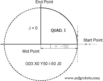 Quad I from 0⁰ to 90⁰ – Circular Interpolation Concepts
| ||||||||||||
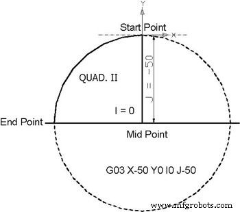 Quad II from 90⁰ to 180⁰ – Circular Interpolation Concepts
| ||||||||||||
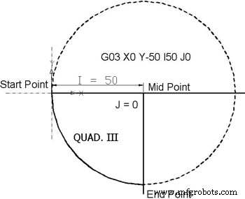 Quad III from 180⁰ to 270⁰ – Circular Interpolation Concepts
| ||||||||||||
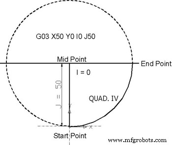 Quad IV from 270⁰ to 0⁰ – Circular Interpolation Concepts
| ||||||||||||
Read Other Parts of this Article
- Circular Interpolation Concepts & Programming Part 1 (Concepts)
- Circular Interpolation Concepts & Programming Part 2 (Use of R)
- Circular Interpolation Concepts & Programming Part 3 (Use of I J K)
- Circular Interpolation Concepts & Programming Part 4 (Unknown R)
- Circular Interpolation Concepts & Programming Part 5 (Examples)
- Circular Interpolation Concepts & Programming Part 6 (Uses & Exercises)
CNC Machine
- CNC G02 Circular Interpolation (Clockwise) – Practical G‑Code Programming Example
- CNC Program Example: G03 Circular Interpolation – Master the Math Behind CNC Machining
- Mastering Circular Interpolation on CNC Machines: Programming with R – Part 2
- Mastering Circular Interpolation: Concepts & Programming – Part 1
- Master CNC Milling: G02 & G03 Circular Interpolation Programming Guide
- Master Circular Interpolation: Step-by-Step Programming Example #2
- Master Circular Interpolation: Programming Example 1
- Circular Interpolation for CNC Machining: Practical Uses & Exercises – Part 6
- Circular Interpolation Techniques: Advanced G90/G91 Programming with CNC Examples
- Mastering Circular Interpolation: Part 4 – Calculating Arc Radius When R Is Unknown