



Ladder Logic in PLC Programming: Fundamentals & Real‑World Examples
Ladder logic is one of the five programming languages defined by the IEC 61131‑3 standard. It remains the most widely adopted due to its intuitive, schematic‑style representation that mirrors hard‑wired relay logic.
By the end of this article you will be able to read a typical industrial program and understand precisely how a machine’s control logic operates.
Prefer a visual walkthrough? Watch the video below or continue reading for a detailed, step‑by‑step explanation.
Electrical Schematic
The first PLC language was created to look like an electrical ladder diagram, making it immediately familiar to electricians and maintenance technicians. Beyond aesthetics, this format facilitates rapid troubleshooting—seeing a rung evaluate to True or False is far quicker than debugging code line by line.
Below is a classic motor start/stop circuit. The start button, stop button, and control relay (CR1) are wired together so that pressing the start button energises CR1. Once CR1 is energised, contacts 8 and 6 close, keeping CR1 powered even after the start button is released. Contacts 1 and 3 then close to energise the motor. Releasing the stop button opens the path to CR1, causing the motor to stop.
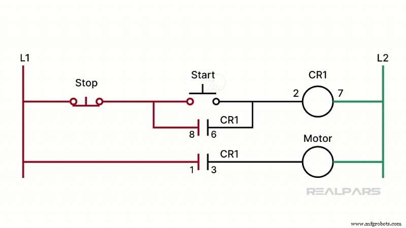
In industrial practice, the relay‑ladder version of this circuit is preferred because it clearly maps circuit actions. Older hard‑wired designs required rewiring whenever a component failed—PLCs eliminate that need by removing physical wiring and most of the hardware.
How Ladder Logic Works
In a PLC‑based motor start/stop sequence, the start and stop buttons become separate PLC inputs. The motor itself is driven by a PLC output. The ladder‑logic program evaluates the state of the inputs and controls the output accordingly.
Basic PLC Instructions
All PLC vendors use graphical symbols that are largely identical, though the names differ. The three most common instructions are:
- Normally Open (NO) Contact – Siemens calls it NO; Allen‑Bradley uses XIC (Examine If Closed). A closed contact returns TRUE, an open contact FALSE.
- Normally Closed (NC) Contact – Siemens calls it NC; Allen‑Bradley uses XIO (Examine If Open). Closed equals TRUE, open equals FALSE.
- Coil (Output Energise) – Siemens calls it a coil; Allen‑Bradley calls it OTE. The coil changes the state of an output when the rung evaluates to TRUE.
These symbols are purely visual; they do not represent physical contacts.
Constructing a Ladder Rung
Think of the left and right vertical lines as power rails. A rung connects the left rail to the right rail through a series of instructions. The left rail supplies logical power; for an output on the right rail to energise, a continuous path of TRUE instructions must exist.
In the motor start example, the rung might read: Start_Button → Stop_Button → Motor_Start. When the start button is pressed, the Start_Button instruction becomes TRUE, creating a logical path that energises Motor_Start. The Motor_Start coil then writes a TRUE value to its designated memory location, which in turn drives the motor.
Because the Motor_Start instruction is a coil, it remains TRUE after the start button is released, creating a latch that keeps the motor running until the stop button is pressed, which sets the Stop_Button instruction to FALSE and breaks the logical path.
Analyzing an Overhead Door Ladder Logic
Let’s examine a more complex example: an overhead door controller. The console has three pushbuttons and three indicator lamps. The rung logic shows that the Door_Shut instruction is TRUE (so the SHUT lamp is on) while Door_Ajar is FALSE (AJAR lamp is off).
Notice the STOP instruction is an XIO (normally closed). Since it is currently TRUE, the PLC memory holds a logic 0, indicating that the physical STOP switch is normally open.
Related Course
PLC Programming
Learn to program PLCs in a practical, hands‑on format. Courses cover Allen‑Bradley, Siemens, Omron, CODESYS, Wago, Schneider, and more.
Wrap‑Up
We’ve taken you from a seemingly cryptic diagram to a clear understanding of how ladder logic translates physical inputs into machine actions. Whether you’re interpreting a Siemens NO contact, an Allen‑Bradley XIC, or a Phoenix Contact coil, the underlying logic remains the same: follow the TRUE and FALSE states to uncover the system’s behavior.
Automation Control System
- Precision Machining Tech Review – February 2022: Automation & Robotics Insights
- OnRobot Opens Singapore HQ to Boost EOAT Solutions in Southeast Asia
- Top 4 Intelligent Automation Trends Shaping 2021: Insights & Opportunities
- Autoware Empowers Small Manufacturers with Advanced AI and Industry 4.0 Solutions
- Cloud Computing: Revolutionizing the Electric Vehicle Landscape
- Survival of the Fastest: How Speed Drives Modern Business Success
- Advanced Welding Automation Equipment: Boost Efficiency & Quality
- Key Indicators You Should Upgrade Your Industrial Control System
- Robotics Revolutionizing Manufacturing: AI-Powered Machines Reshape Production
- Increase Industrial Robot Uptime with Castrol Advanced Lubricants