


Designing Finite State Machines: From Concept to Implementation
Until now we have focused on combinational logic, where outputs depend solely on current inputs. In many real‑world applications, circuits must retain a memory of past inputs and adjust their outputs accordingly. Such circuits are known as sequential circuits.
This article walks through the end‑to‑end process of designing a sequential circuit, illustrated with a practical example: a digital quiz game that must generate a single‑clock‑cycle HIGH pulse each time a user presses a button.
Step 1 – Define the Requirement
Begin by articulating the desired behavior in plain language:
"We need a secondary circuit that emits a single HIGH pulse for one clock cycle when the button is pressed, and ignores further presses until the button is released and pressed again."
Step 2 – Draw the State Diagram
The state diagram visualizes the machine’s operation. Each circle represents a state, while arrows indicate transitions triggered by the input each clock cycle. The diagram below is a Moore finite state machine, where the output depends only on the current state.
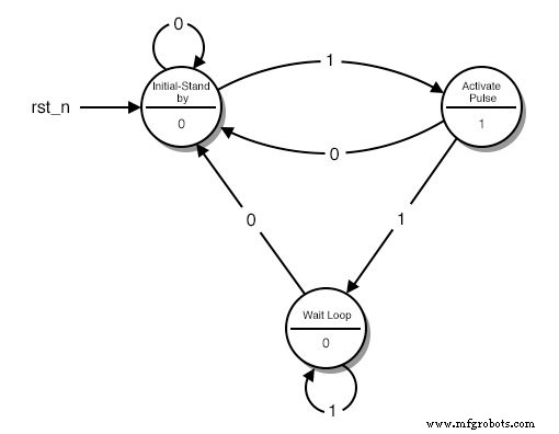
State descriptions:
- Stand‑by – initial waiting state.
- Activate Pulse – generates the HIGH output.
- Wait Loop – holds the LOW output until the button is released.
The arrows are labeled with the input value that triggers the transition. For example, from the Stand‑by state a ‘1’ input moves the machine to Activate Pulse; a ‘0’ keeps it in Stand‑by.
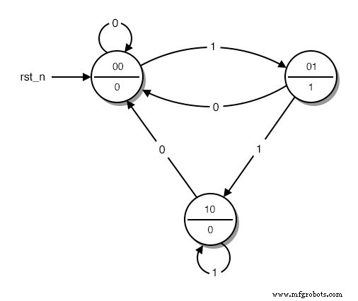
Step 3 – Encode States in Binary
Assign binary codes to each state, starting with 0 for the initial state. The encoding below uses two bits, sufficient for the three states.
Step 4 – Construct the State Table
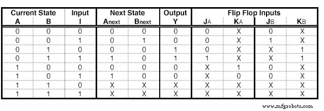
The state table lists all combinations of current state and input, along with the next state and output. Columns correspond to current state bits, input bits, next state bits, and output bits. For this example the table is shown below.
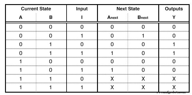
Key points:
- Each row covers every possible binary combination of state and input.
- Rows that correspond to nonexistent states are marked with don’t‑care (X).
- The output column reflects the Moore output, independent of the input.
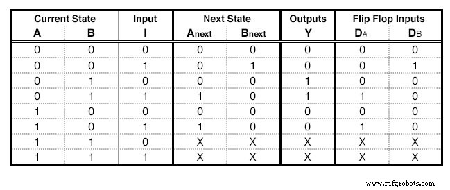
Step 5a – Prepare for D‑Flip Flop Implementation
To implement the machine we typically use flip‑flops. For a D‑flip‑flop, the input required to reach the next state is simply the next state value itself. Extend the state table with a column for each D input.
Step 5b – Prepare for JK‑Flip Flop Implementation
If a JK‑flip‑flop is chosen, two columns (J and K) are added per flip‑flop. Their values are derived from the JK excitation table:
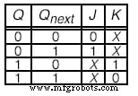
Example mapping: to transition from 0 to 1, set J=1 and K=X (don’t‑care).
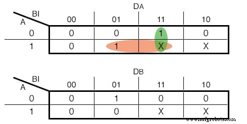
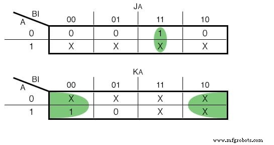
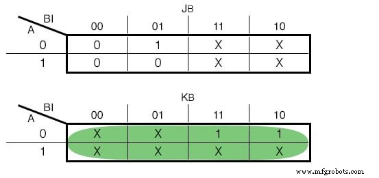
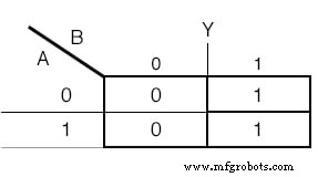
Step 6 – Derive Boolean Functions via Karnaugh Maps
Use Karnaugh maps to simplify the expressions for each flip‑flop input and for the output. The maps below illustrate the process for both D and JK implementations.
D‑flip‑flop inputs:
JK‑flip‑flop inputs:
Output function:

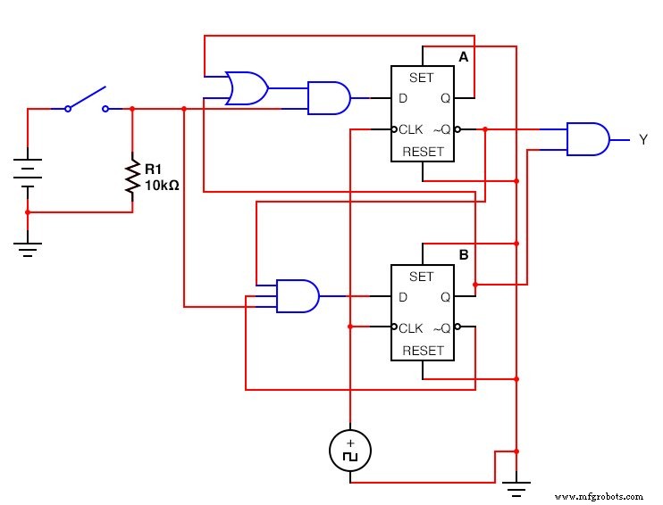
Step 7 – Build the Physical Circuit
With the Boolean equations in hand, assemble the circuit using flip‑flops and logic gates. Remember to connect the clock to all flip‑flops. The completed D‑flip‑flop design is shown below.
The JK‑flip‑flop version looks like this:
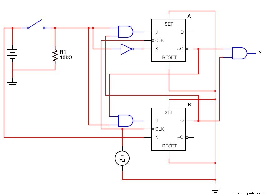
Once assembled, the circuit will generate a clean one‑clock‑cycle HIGH pulse for each button press, regardless of how long the button is held.
Key Takeaways
- Sequential logic retains memory of past inputs, enabling dynamic behavior.
- Finite State Machines provide a rigorous framework for modeling such behavior.
- Flip‑flops implement the FSM in hardware, translating state transitions into physical outputs.
- A systematic design flow—requirements, diagram, encoding, table, logic synthesis, and assembly—ensures reliable circuits.
Industrial Technology
- Hysteresis in Thyristors: How Positive Feedback Enables Latching
- Vending Machines: A $36.6B U.S. Industry Powerhouse
- Voting Machines: History, Technology, and Standards
- Building State Machines with Test‑Driven Development in Embedded C
- Build a Digital Watch on Arduino Using a Finite State Machine
- Explore 15 Essential Milling Machine Types for Precision Metalwork
- Upgrade Legacy Machines for Industry 4.0 Success
- Four Essential CNC Machine Types for Precision Manufacturing
- Comprehensive Guide to Precision Grinding Machines
- Versatile Milling Machines: Cutting, Drilling, and More