


Shift Registers: Fundamentals, Applications, and Design Variants
Shift registers are a cornerstone of sequential logic circuits, functioning similarly to counters but with a focus on data flow rather than counting.
Unlike combinational logic, which reacts solely to present inputs, sequential logic retains a memory of past events. This memory capability allows shift registers to produce a precise, discrete delay of a digital signal or waveform.
When a waveform is synchronized to a clock—a regular square wave—a shift register delays the data by “n” clock cycles, where “n” is the number of stages in the register. For example, a four‑stage register postpones the input data by four clocks before it appears at the output.
Each stage is typically a D‑type or JK‑type flip‑flop acting as a delay element. Historically, very long shift registers (hundreds of stages) were used as a form of digital memory, an approach now replaced by modern RAM. This legacy mirrors the acoustic mercury delay lines once employed in early computers.
Shift registers also play a vital role in serial data transmission. Over distances ranging from meters to kilometers, they convert parallel data into a serial stream, replacing many slow parallel wires with a single high‑speed serial link. On shorter runs—tens of centimeters—they facilitate data transfer between microprocessors and peripherals such as ADCs, DACs, display drivers, and memory modules, thereby reducing board wiring.
Some specialized counters use shift registers to generate repeating waveforms, while longer registers with feedback can produce pseudo‑random noise patterns that appear as truly random sequences.
Basic shift registers are classified by their input and output configurations:
- Serial‑in / Serial‑out (SISO)
- Parallel‑in / Serial‑out (PISO)
- Serial‑in / Parallel‑out (SIPO)
- Universal Parallel‑in / Parallel‑out (UPIO)
- Ring counter
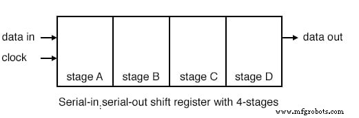
The diagram above illustrates a 4‑stage SISO shift register. Data entered at the input is delayed by four clock periods before reaching the output. After the first clock, the input data appears at stage A; with each subsequent clock, the data propagates to the next stage until, after the fourth clock, it emerges at the output.
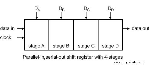
In a parallel‑in / serial‑out configuration, all four stages load data simultaneously. The register then shifts the data out one bit per clock pulse. With a 4‑stage register, four pulses are needed to transfer the entire word. The output retains the data from the final stage (D) until the first clock, then from C, B, and A in subsequent intervals.
When additional input devices (e.g., switches) are connected to the parallel inputs D_A through D_D, a microprocessor can read the collective state using only a single data pin and a clock pin—an efficient method for handling multiple inputs without extra I/O.
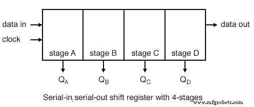
After loading, each data bit appears at its corresponding output (Q_A–Q_D) following successive clock pulses, enabling direct driving of LEDs, relays, horns, or other external circuits.
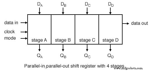
A universal shift register merges the functionalities of both PISO and SIPO, allowing parallel loading, serial shifting, and bidirectional data movement. Although this flexibility increases pin count, it offers a single device for a wide range of data handling tasks.
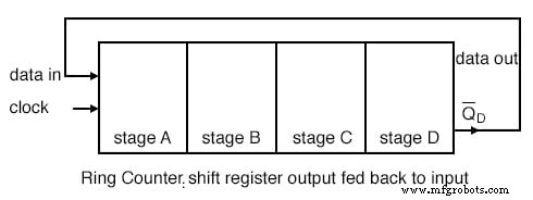
Connecting the serial output back to the serial input creates a ring counter, perpetually cycling data as long as clock pulses continue. If the feedback path inverts the output before re‑input, the ring counter can start from any arbitrary state without a dedicated loading phase.
Related Worksheets
Industrial Technology
- Serial‑In, Serial‑Out Shift Registers: Fundamentals and Practical Applications
- Parallel‑to‑Serial Shift Registers (PISO): Design, Operation, and Applications
- Serial‑In, Parallel‑Out Shift Registers: Converting Serial Data to Parallel for Efficient I/O Expansion
- Universal Shift Registers: Parallel‑In/Parallel‑Out with Bidirectional Shift Control
- Understanding AC Phase Shift: How Waveforms Lead and Lag
- Foundations and Advancements of AC Motor Technology
- Controlling 32 LEDs with Arduino Nano and 4x 74HC595 Shift Registers – A Beginner’s Guide
- Data Science Unveiled: Core Concepts, Types, and Career Opportunities
- Li‑Fi Explained: History, Advantages Over Wi‑Fi, and Real‑World Applications
- Straton Runtime: Integrating PLCNext Engineer with IEC61850 for Seamless Data Exchange