


Understanding AC Phase Shift: How Waveforms Lead and Lag
When two or more alternating‑current (AC) voltages or currents are not synchronized—meaning their peaks and zero crossings do not align—we say they are out of phase. This phenomenon, known as a phase shift, is a fundamental concept in AC circuit analysis.
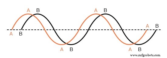
Two waveforms that are not synchronized.
The two curves in the figure above (Wave A and Wave B) have identical amplitude and frequency, yet they are displaced in time. By using the standard sine‑wave representation—0 ° at zero amplitude, 90 ° at peak positive, 180 ° back to zero, 270 ° at peak negative, and 360 ° returning to zero—we can quantify this displacement with an angle measured in degrees.
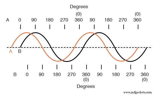
Wave A leads Wave B by 45°.
Additional examples illustrate how varying the angle changes the relative timing between two identical‑frequency waveforms:
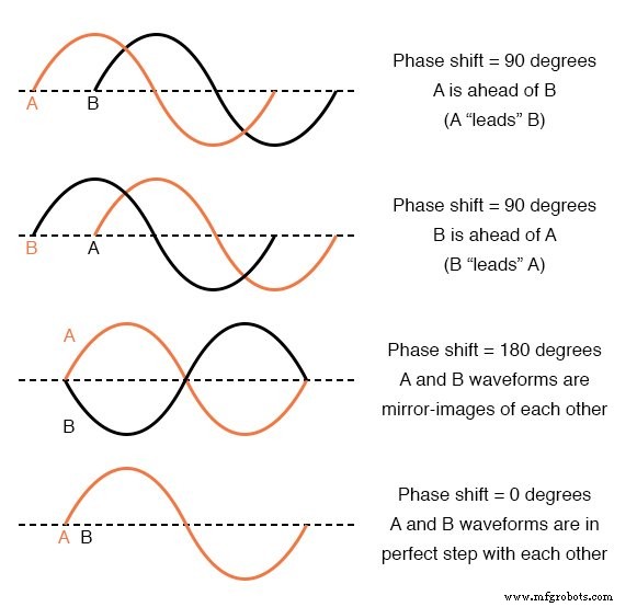
Illustrations of different phase shifts.
Because the frequency is the same, the phase difference remains constant throughout the signal. We therefore describe a relationship such as "Voltage A is 45° out of phase with Voltage B." The waveform that arrives first is said to be leading, while the one that follows is lagging.
Phase shift is inherently a relative measure; no waveform possesses an absolute phase without a reference. In practice, the supply voltage of an AC system serves as the reference point, defined as "0°". All other voltages and currents are expressed relative to this reference.
Unlike direct current (DC) analysis, AC calculations must account for both magnitude and phase. Operations such as addition, subtraction, multiplication, and division are performed on complex numbers, which naturally encode amplitude and phase information. Mastery of complex numbers is therefore essential for accurate AC circuit analysis.
For a deeper dive into the mathematics that underpins this topic, see the next chapter, which is devoted entirely to complex numbers.
Key Takeaways
- Phase shift refers to the relative timing difference between two or more waveforms.
- It is expressed in degrees, based on the standard sine‑wave phase axis.
- A leading waveform is ahead of another; a lagging waveform is behind.
- AC analysis requires both amplitude and phase, and is performed using complex numbers.
Related Worksheet
- Trigonometry for AC Circuits Worksheet
Industrial Technology
- Low‑Voltage AC Power Supply: Phase‑Shift Circuit Components & Best Practices
- Shift Registers: Fundamentals, Applications, and Design Variants
- Phase Shift Oscillator & Varactor Multipliers: Design Principles & Applications
- Representing AC Voltages and Currents as Vectors
- Vector Addition and AC Voltage Superposition: A Practical Guide
- Phase Rotation in Three‑Phase Alternators: Mechanics, Detection, and Wire Reversal
- Designing Polyphase AC Motors: Fundamentals and Practical Startup Techniques
- Understanding Harmonic Phase Sequences in Three-Phase Power Systems
- Measuring Frequency and Phase in AC Power Systems
- Understanding Phase Meters: Accurate Measurement of Electrical Power