


Vector Addition and AC Voltage Superposition: A Practical Guide
Vectors behave like numbers on a number line: they can be added, subtracted, multiplied, and divided. The most intuitive operation is addition, and this article walks through it step by step, using both geometric vectors and alternating‑current (AC) voltage sources.
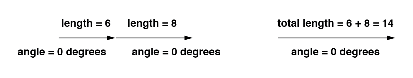
When two vectors share the same direction (i.e., their angles coincide), their magnitudes simply add, just as with scalars:
In electrical terms, connecting two AC voltage sources that share the same phase angle in series produces a combined voltage equal to the sum of the individual voltages—exactly what you expect when you wire DC batteries end‑to‑end:
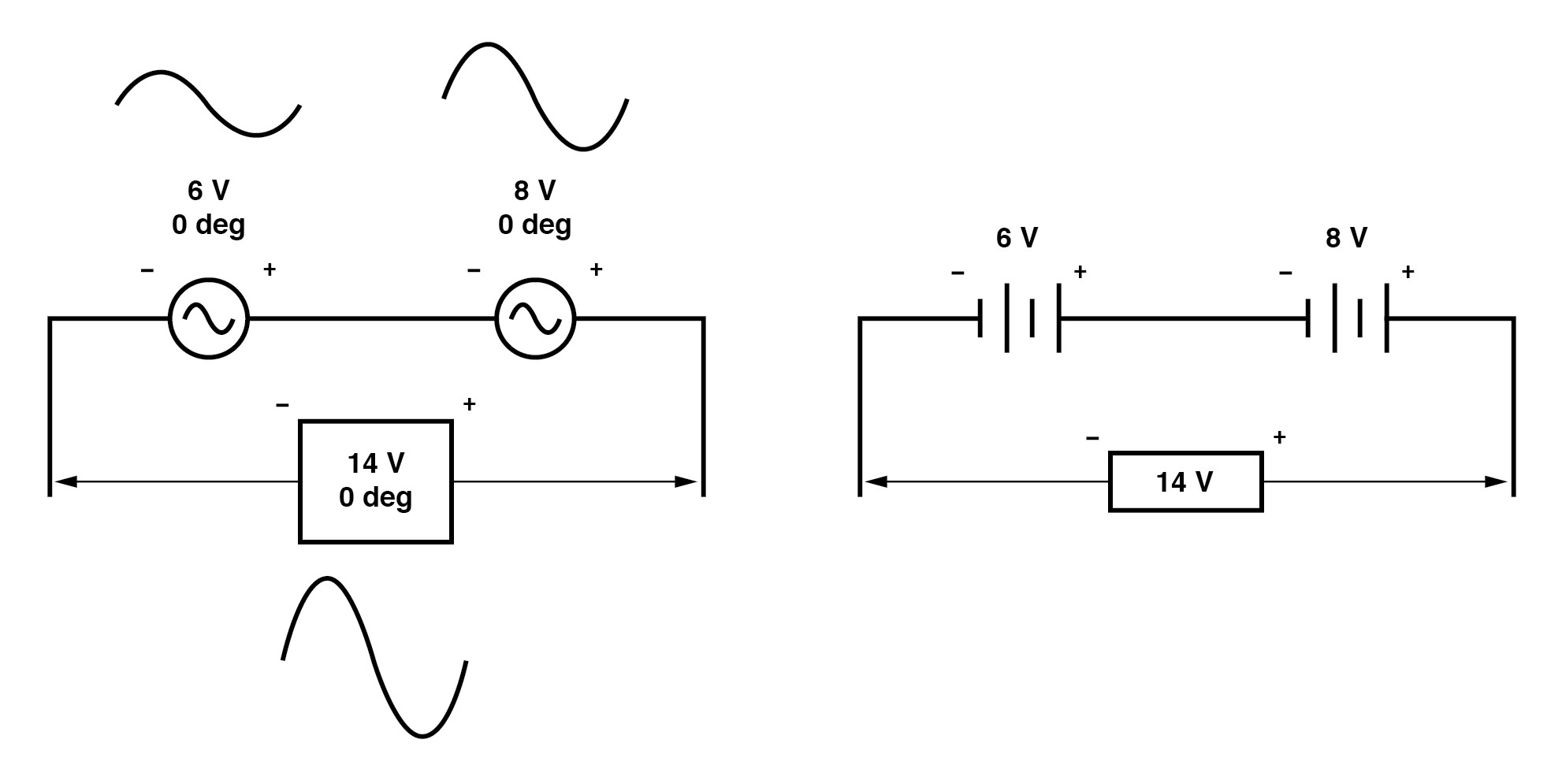
Even though AC does not have a permanent polarity like DC, the (+) and (–) symbols on the leads indicate how each source’s phase angle is referenced. These markings are essential for correctly adding or subtracting voltages, a point that becomes clearer in the next example.
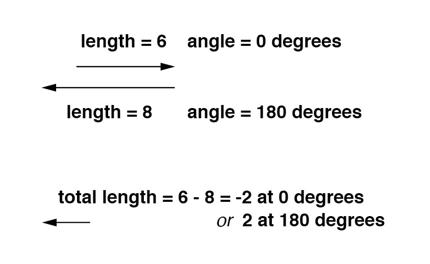
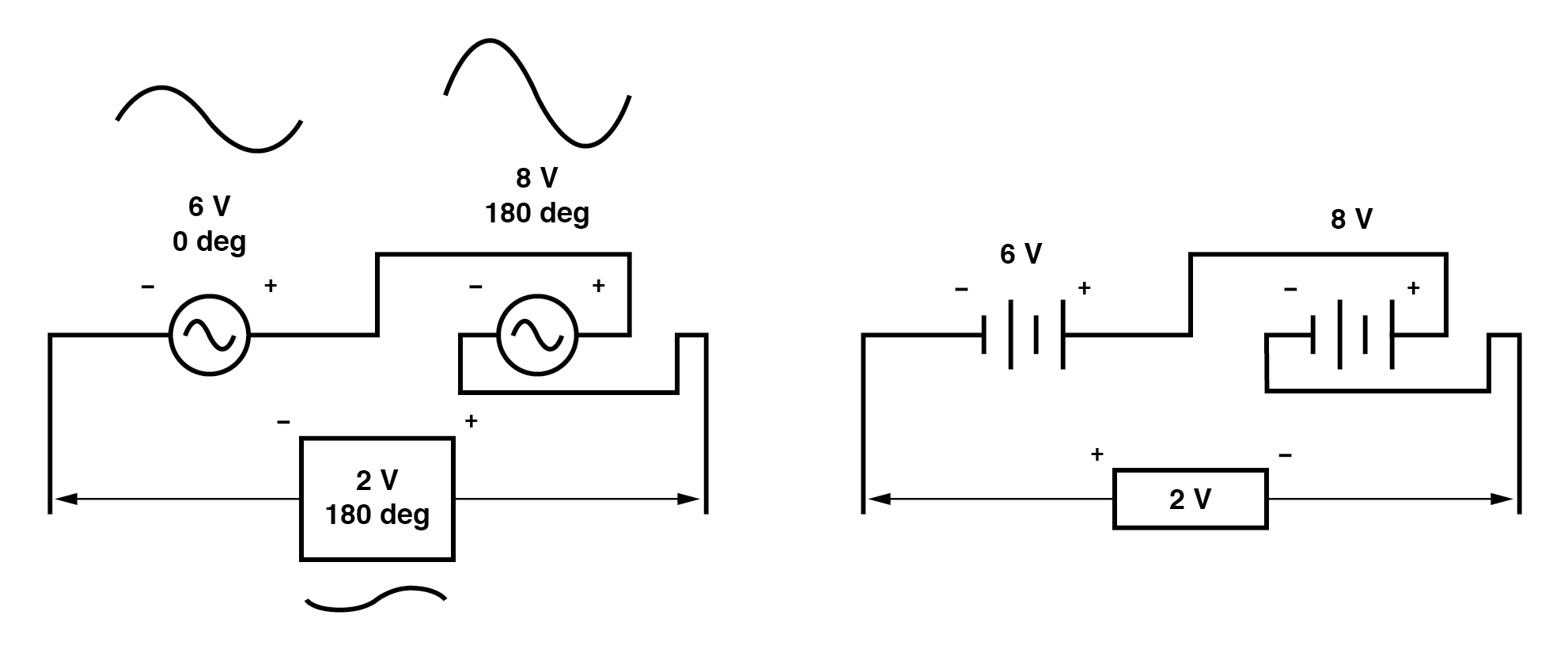
When two vectors point in opposite directions—180° out of phase—their magnitudes subtract, mirroring the subtraction of positive and negative scalars:
Analogously, two opposing AC sources in series will produce a net voltage that is the difference of the two, similar to two DC batteries wired in reverse:
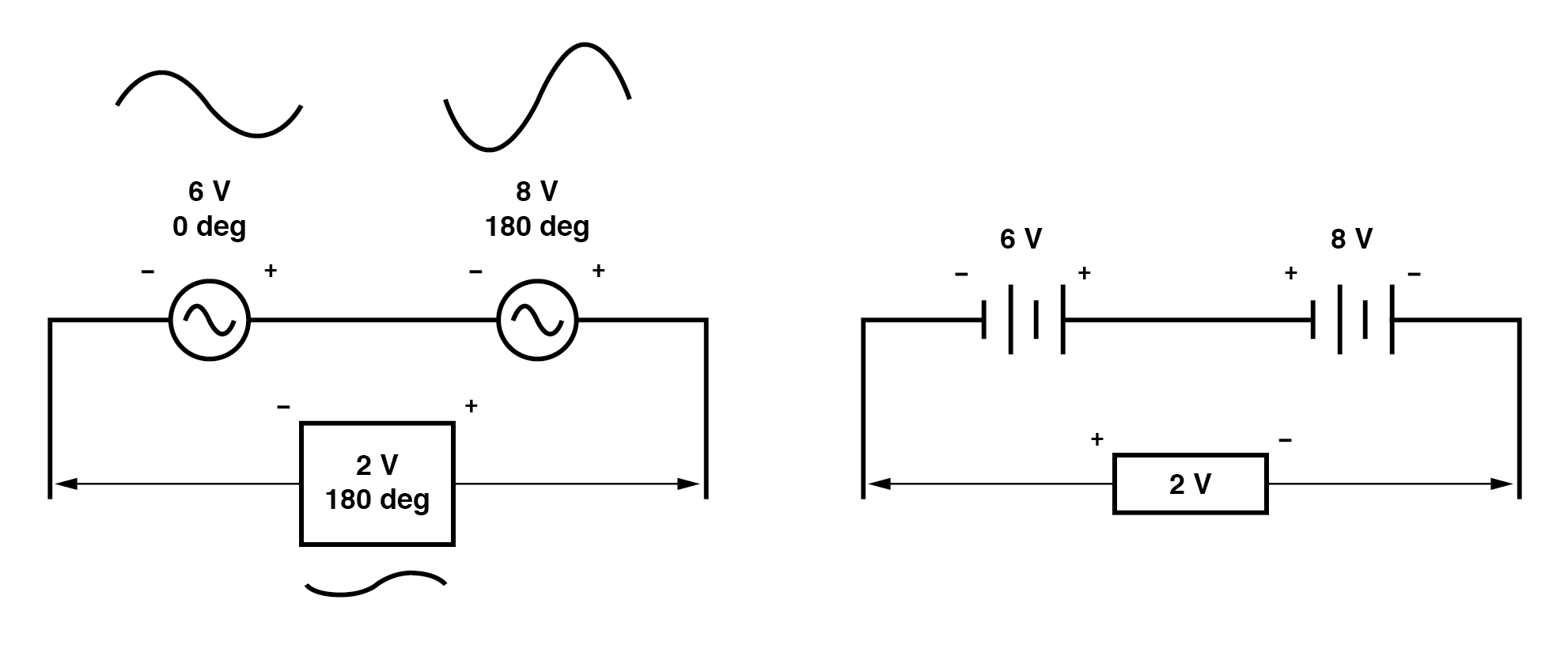
Determining whether two AC sources oppose each other requires examining both their polarity markings and their phase angles. In the diagram above, the 6‑V source shows – to +, and the 8‑V source shows – to +, suggesting an additive arrangement in DC. However, because one source is at 0° and the other at 180°, they actually oppose each other, yielding a net voltage of only 2 V.
Reversing the wire connections on the 8‑V source (effectively rotating its phase by 180°) results in the same net voltage, but with the polarity markings flipped. The underlying physics remains unchanged: the two voltages still subtract.
In all cases, the resultant voltage can be expressed in two equivalent forms: either 2 V at 180° with the (–) symbol on the left and (+) on the right, or 2 V at 0° with (+) on the left and (–) on the right. A wire reversal on an AC source is mathematically identical to a 180° phase shift.
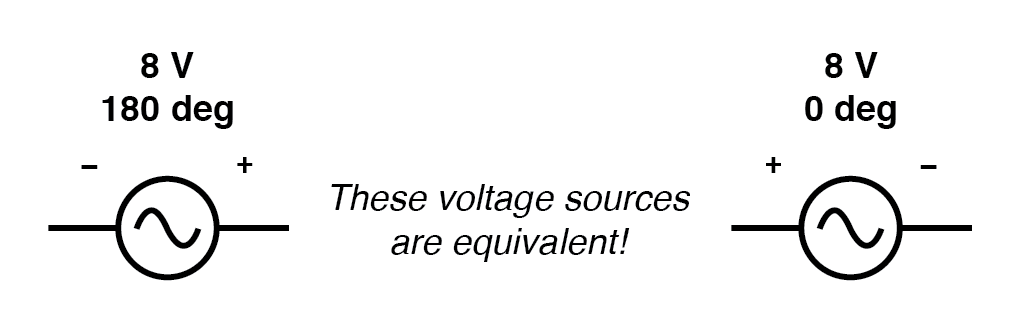
Two ways to represent the same resulting voltage.
For further practice, refer to the following worksheets:
- AC Phase Worksheet
- AC Network Analysis Worksheet
Industrial Technology
- Simple Analog Averaging Circuit: A Practical Voltage Averager
- Low‑Voltage AC Power Supply: Phase‑Shift Circuit Components & Best Practices
- Build a High‑Gain Differential Amplifier That Works as an Op‑Amp
- Binary Addition Explained: Rules, Examples, and Its Role in Digital Computers
- Tachogenerators: Precision Speed Measurement for Industrial Motors and Equipment
- Understanding AC Waveforms: Sine Waves, Frequency, and Oscilloscope Basics
- Understanding AC Phase Shift: How Waveforms Lead and Lag
- Vector Addition and AC Voltage Superposition: A Practical Guide
- Complex Vector Addition: How AC Voltages Combine
- DIY 5V Cell Phone Charger Circuit – Convert 230V AC to 5V DC Safely