


How Voltage Dividers Set Gain in Non‑Inverting and Inverting Op‑Amp Amplifiers
Adding a voltage divider to the negative‑feedback path of an op‑amp means only a fraction of the output feeds back to the inverting input. The result is an output that is a predictable multiple of the input. The power‑supply connections are omitted here for simplicity.
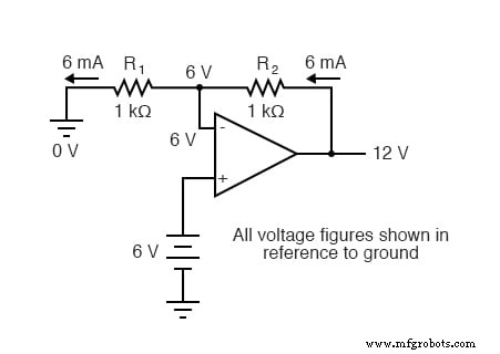
With R1 = R2 = 1 kΩ and a 6‑V input, the op‑amp must produce 12 V at its output to keep the inverting input at 6 V. The divider forces the output to be twice the input.
We can also view the circuit by calculating the current through R1. The left side of R1 sits at ground, while the right side is at 6 V, so 6 V drops across R1 and 6 mA flows from right to left. Because the op‑amp inputs draw negligible current, the same current flows through R2, generating another 6 V across it. Adding the two voltages gives the 12 V output.
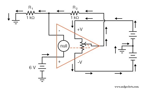
Where does the 6 mA go? It flows from the positive supply, through the op‑amp output pin, through R2, through R1, and to ground. The 6‑V source merely forces the op‑amp to balance the two inputs; it does not supply current to the divider.
Changing the resistor values changes the overall gain. The general gain formula is
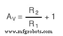
The gain can never fall below 1. If R2 were zero ohms, the circuit becomes a voltage follower with a unity gain. Raising R2 relative to R1 boosts the gain arbitrarily.
Because the output polarity matches the input, this configuration is called a non‑inverting amplifier.
Role of the Op‑Amp’s Differential Gain
Once negative feedback is in place, the op‑amp’s internal differential gain (e.g., 200 000 or 250 000) has negligible effect on the overall circuit behavior. The external resistor ratio dictates the closed‑loop gain, unlike transistor‑based amplifiers where β strongly influences performance.
Inverting Amplifier with a Grounded Non‑Inverting Input
Now consider the input applied to the bottom of the divider while the non‑inverting input is grounded:
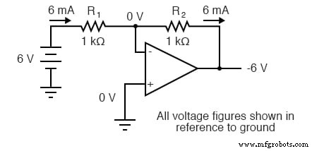
The negative feedback forces the inverting input to a virtual ground (0 V). With R1 = R2 = 1 kΩ and a 6‑V input on the left side, the output must swing to –6 V to maintain the middle node at 0 V.
The gain for this configuration is given by
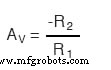
Here the gain can be less than 1, and the output polarity is opposite to the input, which is why it is called an inverting amplifier.
Takeaway
- Directly connecting the op‑amp’s inverting input to its output creates a voltage follower with unity gain.
- Using a voltage divider for negative feedback turns the circuit into a non‑inverting amplifier; gain = 1 + R2/R1 and output polarity matches the input.
- Applying the input to the bottom of the divider (non‑inverting input grounded) yields an inverting amplifier; gain = –R2/R1 and output polarity is inverted.
- In all cases, the external resistor ratio sets the closed‑loop gain, rendering the op‑amp’s internal differential gain irrelevant.
Industrial Technology
- Exploring Voltage Addition with Series Battery Connections
- Voltage Divider Lab: Design, Measurement, and Kirchhoff’s Voltage Law Verification
- Thermoelectricity: Understanding Thermocouples and the Seebeck Effect
- Potentiometric Voltmeter: Precise Voltage Measurement with Minimal Loading
- Understanding Amplifier Feedback: Positive vs Negative, and Practical Applications
- Understanding Negative Feedback in Op‑Amps: Voltage Followers and Stability
- Lever Analogy: Clarifying Divided Feedback in Amplifiers
- Positive Feedback in Op‑Amp Circuits: Hysteresis, Comparators, and Oscillators
- Tachogenerators: Precision Speed Measurement for Industrial Motors and Equipment
- Understanding AC Waveforms: Sine Waves, Frequency, and Oscilloscope Basics