


Positive Feedback in Op‑Amp Circuits: Hysteresis, Comparators, and Oscillators
While negative feedback is essential for tuning op‑amp gain, bandwidth, and stability, positive feedback offers its own unique advantages. By feeding the output back to the non‑inverting input, an op‑amp can lock into one of two saturated states, creating hysteresis that is invaluable in comparator and oscillator designs.
The core idea behind negative feedback is to bring the output back toward equilibrium. Without it, even a minuscule differential input drives the op‑amp to saturation, behaving like a simple comparator.
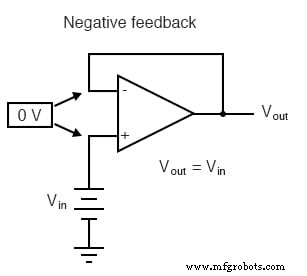
With negative feedback—by routing the output back to the inverting (-) input—the op‑amp’s enormous differential gain is tamed. The output settles at the value that balances the two input voltages, producing a predictable, linear response governed by the external feedback network.
Positive Feedback in an Op‑Amp
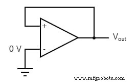
Positive feedback routes the output to the non‑inverting (+) input. The simplest configuration is a direct wire from output to (+) input, leaving the inverting (-) input disconnected. If the (-) input is grounded, the op‑amp’s output follows the sign of the voltage at the (+) input, driving itself to full positive or negative saturation.
Because the output is already saturated, the circuit becomes bistable: it remains in the current saturated state until an external voltage applied to the (-) input exceeds the current output level. This property, known as hysteresis, is the cornerstone of many digital‑logic circuits.
Applications of Positive Feedback
1. Comparator with Hysteresis
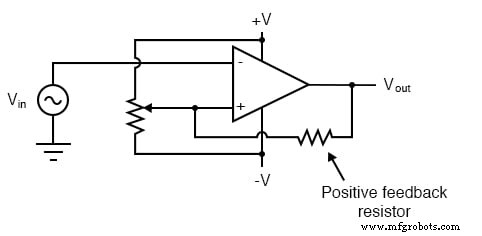
A comparator without hysteresis will toggle its output whenever the input crosses the reference voltage, leading to glitches in noisy signals. Adding a small positive‑feedback resistor establishes two distinct reference levels—an upper level when the output is high and a lower level when it is low. The output then only switches when the input exceeds these thresholds, resulting in a clean square‑wave output even in the presence of distortion.
2. Astable Oscillators
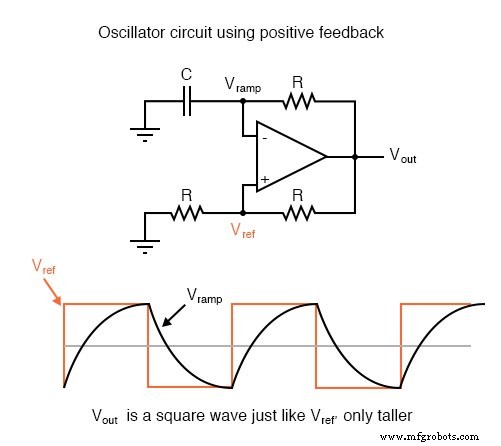
By combining positive feedback with a delayed negative feedback path (typically an RC network), an op‑amp can generate a continuous square‑wave. The output alternates between its saturated states, and the RC time constant sets the oscillation frequency.
Review
- Negative feedback establishes equilibrium; positive feedback creates hysteresis (latching).
- An oscillator is an astable device that produces a periodic or pulsing output.
Related Worksheet
Industrial Technology
- Common‑Emitter Amplifier: Design, Measurement, and Feedback Techniques
- Build a High‑Gain Differential Amplifier That Works as an Op‑Amp
- Precision Voltage Follower: Mastering Op‑Amp Feedback for Accurate Signal Tracking
- Digital Logic with Feedback: From Deterministic Gates to Multivibrators
- Integrating (Single‑Slope) ADCs: Principles, Advantages, and Dual‑Slope Alternatives
- Understanding Amplifier Feedback: Positive vs Negative, and Practical Applications
- Understanding Negative Feedback in Op‑Amps: Voltage Followers and Stability
- How Voltage Dividers Set Gain in Non‑Inverting and Inverting Op‑Amp Amplifiers
- Tachogenerators: Precision Speed Measurement for Industrial Motors and Equipment
- Timers & Multi-Vibrators: Types, Functions, and Digital Applications