


Understanding Differentiator and Integrator Op‑Amp Circuits
By incorporating electrical reactance into the feedback loop of an op‑amp, the output can be made to respond to changes in the input voltage over time. Drawing their names from the corresponding calculus operations, the integrator produces a voltage proportional to the product of the input voltage and time, while the differentiator (not to be confused with differential) generates a voltage proportional to the rate of change of the input voltage.
What is Capacitance?
Capacitance measures a capacitor’s resistance to changes in voltage. A larger capacitance yields a larger current for a given rate of voltage change, because the capacitor charges or discharges to counter the voltage shift. The relationship is expressed simply as:
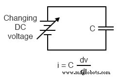
The dv/dt term is the calculus representation of voltage change per unit time. For example, raising a DC supply from 15 V to 16 V over one hour results in a very small current (dv/dt = 1 V/3600 s). The same 1 V step taken over one second produces a current 3600 times larger, illustrating how the rate of change drives the capacitor current.
To give concrete numbers: a 47 µF capacitor experiencing a linear voltage rise of 3 V/s will conduct a current of (47 µF)(3 V/s) = 141 µA.
We can build an op‑amp that measures this voltage change by converting the capacitor current into a proportional output voltage:
The Virtual Ground Effect
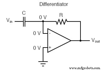
The capacitor’s right terminal is held at 0 V by the virtual‑ground property of the op‑amp. Consequently, the current through the capacitor is solely driven by changes in the input voltage; a steady input produces no current. That current flows through the feedback resistor, generating a voltage drop that appears at the output. A positive, linear rate of input change produces a steady negative output voltage, and a negative rate yields a steady positive output—an inversion that follows the op‑amp’s inverting configuration. Faster rates of change produce larger output magnitudes.
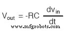
The differentiator’s output voltage is given by:
Rate‑of‑Change Indicators for Process Instrumentation
Beyond analog computing, differentiators serve as rate‑of‑change sensors in process control. For instance, they can monitor the temperature rise in a furnace, triggering alarms or control actions when the rate exceeds safe limits. Analog controllers often embed derivative blocks to stabilize set‑point tracking by limiting rapid excursions that could destabilize the system.
Integration
Conversely, many applications require the opposite operation—integrating the input signal over time. An op‑amp integrator generates an output voltage proportional to the accumulated area under the input waveform. Swapping the capacitor and resistor positions in the previous circuit achieves this behavior:
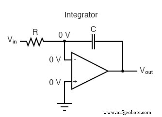
The virtual ground keeps the inverting input at 0 V. With a zero input, no current flows and the output remains constant (its absolute level depends on prior conditions). A constant positive input drives the output negative at a linear rate; a constant negative input drives it positive. The output’s rate of change is directly proportional to the input magnitude.
Formula to Determine Voltage Output
The integrator’s output voltage follows:
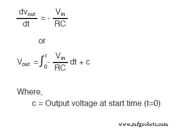
Practical uses include tracking cumulative radiation dose—where the integrator sums intensity over time—or calculating total water flow from a flow meter, a function often called a “totalizer” in industrial instrumentation.
Review
- A differentiator produces a steady output voltage when the input changes linearly.
- An integrator produces a linearly changing output voltage in response to a constant input.
- Both devices are straightforward to build using reactive components—typically capacitors—in the feedback loop.
Related Worksheet
- Linear Computational Circuitry Worksheet
Industrial Technology
- Precision Op‑Amp Integrator Lab: Bias‑Current Compensation & Analog Computation
- Passive Averager and Op‑Amp Summer Circuits: From Averaging to Addition
- Power Supply Circuits: Types, Design Principles, and Performance
- Understanding Power in Electric Circuits: Measurement & Significance
- Voltage Divider Circuits: Mastering Series Resistor Analysis & Potentiometers
- Understanding AC Inductor Circuits: Reactance, Phase Shift, and Power Dynamics
- AC Capacitor Circuits: Capacitive Reactance, Phase Shift, and Power Behavior
- Master Voltage Divider Rule (VDR): Step‑by‑Step Examples for Resistor, Inductor, and Capacitor Circuits
- Schmitt Trigger Explained: Design, Function, and Practical Applications
- Voltage Doubler: A Lightweight, Cost‑Effective Alternative to Transformer‑Rectifier Circuits