


Understanding and Designing an Instrumentation Amplifier
What Is an Instrumentation Amplifier?
An instrumentation amplifier gives engineers the ability to fine‑tune a circuit’s gain by altering just one resistor, unlike a conventional differential amplifier that requires multiple resistor changes. Built on the differential amplifier’s foundation, it adds a single adjustable resistor that unlocks this convenience.
How the Circuit Works
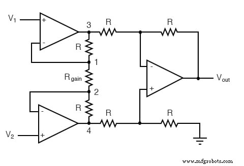
The design combines a buffered differential stage with three additional resistors that connect the two buffer sections. All resistors are equal except for R_gain.
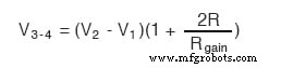
Negative feedback in the upper‑left op‑amp forces the voltage at point 1 (the top of R_gain) to match V_1, while the lower op‑amp locks the voltage at point 2 (the bottom of R_gain) to V_2. This creates a voltage drop across R_gain equal to the difference between V_1 and V_2. Because the op‑amps’ input currents are negligible, the same current flows through the two resistors adjacent to R_gain, producing a voltage drop between points 3 and 4 given by:
The standard differential amplifier on the right then amplifies this drop by a factor of one—provided the surrounding resistors are equal.
Why Use an Instrumentation Amplifier?
Although the layout looks complex, this configuration offers two major benefits:
- Extremely high input impedance at
V_1andV_2, because each connects directly to the non‑inverting input of its op‑amp. - Simple, single‑resistor gain adjustment via
R_gain.
Rearranging the algebra yields the overall voltage gain expression:
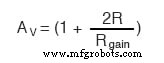
In practice, changing only R_gain is enough to alter the differential gain. While tweaking other resistors can also adjust the gain, it would require perfectly balanced changes to keep the circuit symmetrical. Note that setting R_gain to infinity (open circuit) yields the minimum gain of 1.
Key Takeaway
- An instrumentation amplifier delivers high input impedance and effortless gain control through a single resistor, making it ideal for precision measurement circuits.
Further Reading
- Summer and Subtractor OpAmp Circuits Worksheet
Industrial Technology
- Understanding Amplifier Gain: Voltage, Current, and Power
- Understanding the Common-Emitter Amplifier: Switching, Amplification, and Biasing Techniques
- Common‑Collector Amplifier: Emitter‑Follower Fundamentals & Applications
- Common‑Base Transistor Amplifiers: Design, Analysis, and Applications
- Cascode Amplifier: Combining Common‑Emitter and Common‑Base for Wide Bandwidth and High Input Impedance
- Common-Source JFET Amplifier: Design, Analysis, and Practical Worksheet
- Common‑Source Amplifier (IGFET): Design, Biasing, and Performance
- Common‑Drain Amplifier (IGFET): Design, Function, and Applications
- Common‑Gate IGFET Amplifier: Theory, Design, and Practical Applications
- The Operational Amplifier: Foundations, Features, and Key Applications