


Understanding TRIACs: Bidirectional Power Control in AC Applications
TRIACs are the bidirectional counterparts of silicon controlled rectifiers (SCRs). By connecting two SCRs back‑to‑back, a TRIAC can conduct current in both directions, making it ideal for AC power control.
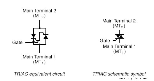
TRIAC: SCR equivalent and schematic symbol.
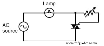
While SCRs find common use in high‑power motor drives and other advanced control systems, TRIACs are most often seen in low‑power, household applications such as lamp dimmers. A typical dimming circuit is shown below, complete with the phase‑shifting resistor‑capacitor network that delays the gate trigger until after the voltage peak.
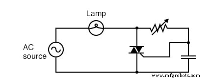
TRIAC phase‑control of power.
One of the main challenges with TRIACs is their tendency to fire asymmetrically. The gate threshold for one polarity can differ from the threshold for the opposite polarity, which introduces even‑order harmonics into the current waveform. In power systems, a cleaner, more symmetrical waveform is desirable because it reduces harmonic distortion and improves overall efficiency.
To improve symmetry, a DIAC can be placed in series with the gate. DIACs have very symmetrical breakover voltages, so they ensure that the TRIAC receives a consistent trigger pulse regardless of polarity. The result is a more uniform firing angle from cycle to cycle.
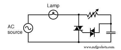
DIAC improves symmetry of control.
In practice, the electrical characteristics of a TRIAC mirror those of an SCR, except that the device is inherently bidirectional. However, it is crucial to remember that the two main terminals—MT1 and MT2—are not interchangeable. Unlike the equivalent model, a TRIAC is fabricated from a single semiconductor structure, and its internal doping profile defines distinct terminal functions.
Consider the following two simple dimmer circuits. The first, with the gate connected to MT2, functions correctly. The second, with the gate connected to MT1, fails to trigger, regardless of the control resistor value.
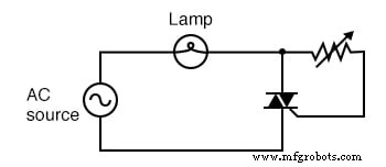
This circuit with the gate to MT2 works.
With the gate swapped to MT1, this circuit does not work.
Therefore, to reliably trigger a TRIAC, always source the gate current from the side opposite the gate terminal—i.e., from MT2. Verify terminal designations in the device’s datasheet or reference guide before wiring.
Key Take‑aways
- TRIACs combine two SCRs for bidirectional AC control.
- They are preferred in simple, low‑power circuits; high‑power applications typically use discrete SCRs.
- DIACs are commonly added to the gate to enforce symmetrical firing.
- MT1 and MT2 are distinct; they must not be swapped.
- Gate current must originate from MT2 for proper operation.
Further Reading
Industrial Technology
- Mastering AC Circuit Equations: Impedance, Reactance & Resonance
- The S‑R Latch: Fundamentals, Race Conditions, and Practical Applications
- Mastering PCB Fabrication: Key Principles for High-Quality Printed Circuit Boards
- The Evolution of Printed Circuit Boards: From Early Beginnings to Modern Technology
- Top 13 Free Circuit Simulators: Trusted Tools for Accurate Design
- Mastering Circuit Traces: The Definitive Guide to PCB Design
- Mastering PCB Assembly: From Blueprint to Finished Product
- Understanding PCB Assembly: Key Techniques & Benefits
- How Printed Circuit Boards Evolved: From Basics to Modern Tech
- How Printed Circuit Boards Revolutionized Electronics