


The S‑R Latch: Fundamentals, Race Conditions, and Practical Applications
A bistable multivibrator has two stable states, hence the prefix bi. One state is called set and the other reset. The most basic form of this device is the set‑reset (S‑R) latch.
To build an S‑R latch, two NOR gates are wired so that each gate’s output feeds back to the other gate’s input, creating the classic cross‑coupled topology shown below:
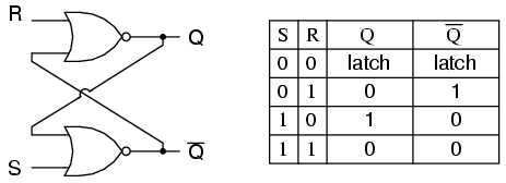
The outputs Q and ¬Q are expected to be complementary. If both inputs S and R are driven high, both outputs fall to 0—an invalid or illegal state for the latch. In contrast, S=1 and R=0 “sets” the latch (Q=1, ¬Q=0), while S=0 and R=1 “resets” it (Q=0, ¬Q=1). When both inputs are 0, the latch holds its previous state.
Identical logic can be expressed in ladder logic, achieving the same results:
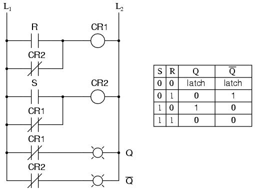
By definition, Q=1 and ¬Q=0 is the set condition; Q=0 and ¬Q=1 is reset. When the circuit is first powered on, both gates or relays are de‑energized, which places the latch in the same output state—an unstable situation. The device will quickly resolve to either set or reset because one component reacts slightly faster than the other.
If the two elements were perfectly matched, they could oscillate like an astable multivibrator during power‑up, never settling into a stable state. Although such perfect matching is rare, a brief oscillation cycle is almost inevitable, making the final state after power‑up unpredictable. This unpredictability stems from a race condition between the two relays (CR1 and CR2).
A race condition occurs when two mutually exclusive events are triggered simultaneously by a single cause. In this latch, the relays’ normally‑closed interlocking contacts prevent both from latching at once. When both coils start de‑energized—such as after a full power cycle—each relay attempts to latch via the other’s contact, and the first to energize wins, forcing the other to remain off. The outcome depends on component tolerances, not on design, so the post‑power‑up state is indeterminate.
To eliminate this race, a time‑delay relay can be inserted to give one relay a clear advantage. The following schematic demonstrates this approach:

Upon power‑up, the delay contact TD1 remains open for one second, preventing CR2 from energizing through CR1. CR1 receives power first, energizes, and then opens its normally‑closed contact, ensuring CR2 cannot latch. The system therefore powers up predictably in the reset state (S=0, R=0).
Race conditions are not limited to relay circuits; they can also appear in solid‑state logic designs and software programs if sequencing is not carefully managed. Identifying and mitigating such conditions is critical in any sequential system.
A common real‑world use of an S‑R latch is motor start‑stop control. A simple ladder logic implementation uses momentary start and stop pushbuttons for S and R, respectively, and a contactor (or a relay) to energize the motor. The standard circuit is shown below:
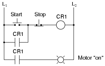
In this setup, the relay contact in parallel with the start button acts as a seal‑in contact, maintaining the relay’s energized state after the start button is released. Pressing the stop button de‑energizes the relay, breaking the seal and stopping the motor. This simple latch functions equivalently to an S‑R latch and avoids the instability seen in the double‑relay design.
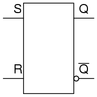
In semiconductor form, S‑R latches are packaged as discrete integrated circuits, identified by the standard symbol below:
Key Takeaways
- A bistable multivibrator offers two stable output states.
- Set is defined as Q=1, ¬Q=0; reset is Q=0, ¬Q=1; an equal output state is invalid.
- In an S‑R latch, activating S sets the circuit; activating R resets it. Simultaneous activation leads to an invalid condition.
- A race condition arises when two exclusive events are triggered at the same time, causing unpredictable results.
Industrial Technology
- NOR Gate SR Latch: Building and Understanding Digital Memory
- Building an Enabled NAND‑Gate SR Latch: Parts, Design, and Operation
- Gated SR Latch: Enhancing Logic Control with an Enable Input
- Mastering the D Latch: A Clean 1‑Bit Memory Circuit
- Understanding TRIACs: Bidirectional Power Control in AC Applications
- The Evolution of Printed Circuit Boards: From Early Beginnings to Modern Technology
- Top 13 Free Circuit Simulators: Trusted Tools for Accurate Design
- Mastering Circuit Traces: The Definitive Guide to PCB Design
- Mastering PCB Assembly: From Blueprint to Finished Product
- Understanding PCB Assembly: Key Techniques & Benefits