


Digital Logic with Feedback: From Deterministic Gates to Multivibrators
In conventional combinational logic, each input combination produces a unique, predictable output. For example, an OR gate follows the truth table shown below:
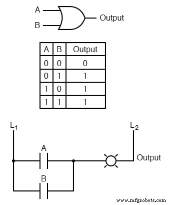
With four possible input states (0‑0, 0‑1, 1‑0, 1‑1), the output is always unambiguous. Whether a circuit contains a single gate or a cascade of many, the output is fully determined by the gate’s truth tables.
Introducing feedback—connecting the gate’s output back to one of its inputs—breaks this determinism. Consider the OR gate with a feedback loop:
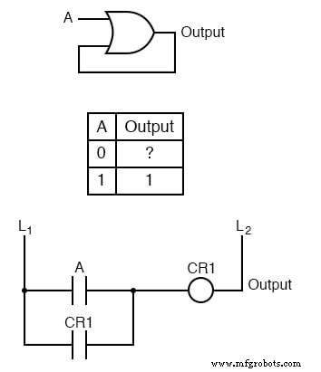
When input A is logic 1, the OR gate forces the output high, and the feedback keeps it high. When A drops to logic 0, the output no longer has a definitive value; it will remain in whatever state it was in prior to the change. In other words, the circuit “latches” the last output value.
Digital circuits that use feedback are called multivibrators. The OR‑gate example is a classic bistable multivibrator, which can stably hold either of two output states—0 or 1—until an input triggers a transition.
Multivibrators come in three main flavors:
- Bistable – two stable states (e.g., flip‑flops).
- Monostable – one stable state with a single, temporary excursion.
- Astable – no stable state; the output continuously oscillates.
A simple astable multivibrator can be built from an inverter with its output fed back to its input:
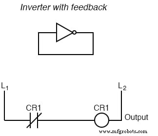
When the inverter input is 0, the output goes to 1; this 1 is fed back as the new input, causing the output to flip to 0. The cycle repeats, generating a high‑frequency square wave (several MHz with solid‑state gates; audio‑range with relay logic).
Historically, such “buzzer” or “vibrator” circuits were essential in early radio, converting steady low‑voltage DC into pulsating DC that could be stepped up by a transformer to produce the high voltages needed for vacuum‑tube amplifiers. Henry Ford’s engineers also used the same principle to supply continuous high voltage for Model T spark plugs.
Today, solid‑state designers still refer to any circuit with multiple vibrators linked together as a multivibrator. While the simple astable example above uses a single inverter, more complex astable designs typically employ multiple gates for better performance.
Among multivibrators, bistable configurations are the most prevalent and useful. They form the basis of memory elements, flip‑flops, and digital registers—cornerstones of modern digital systems.
RELATED WORKSHEETS:
- Latch Circuits Worksheet
Industrial Technology
- Understanding Digital Logic Functions: OR, AND, NOT, and Beyond
- Mastering Logic Simplification with Karnaugh Maps
- Digital Ramp (Counter) ADC: Operation, Benefits, and Limitations
- Understanding Negative Feedback in Op‑Amps: Voltage Followers and Stability
- Positive Feedback in Op‑Amp Circuits: Hysteresis, Comparators, and Oscillators
- Designing Combinational Logic in Verilog Using Continuous Assign Statements
- Implementing Combinational Logic Using Verilog's always Block
- Implementing Sequential Logic Using Verilog 'always' Blocks
- Integrating Legacy Systems for Seamless Digital Transformation
- Digital Logic Board Kit: Components & Setup Guide