


Designing a Four‑Digit 7‑Segment Display with a Single Binary Encoder
In this practical example, we demonstrate how to build a four‑digit 7‑segment display that accepts a 16‑bit binary input—representing a decimal number—and drives the display using a single binary‑to‑7‑segment encoder. The design showcases the power of combinational logic, demultiplexing, and modular design.
The circuit’s overall architecture is illustrated below. It features 16 primary inputs for the number, two additional control inputs to select which digit is active, and 28 output lines that drive the four 7‑segment displays.
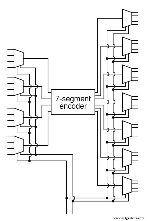
Only the four bits that correspond to the selected digit are forwarded to the encoder; the remaining bits are forced to zero by the demultiplexers, ensuring that the other three digits remain blank.
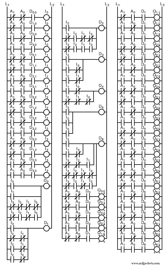
To understand how the individual components cooperate, compare the gate‑level diagram with the equivalent ladder logic shown below. Notice how a complex system is assembled from well‑defined sub‑circuits, allowing designers to reason about the overall behavior without becoming overwhelmed by detail.
While this combinational design is functional, it only displays one digit at a time. To create the illusion of a fully lit four‑digit display, the next step is to introduce a sequential circuit that rapidly cycles through the digits—an approach known as multiplexing. That topic is covered in the following chapters.
Related Worksheets:
- Digital Display Circuits Worksheet
- Sum‑of‑Products and Product‑of‑Sums Expressions Worksheet
Industrial Technology
- Advanced Motor Control Circuits: Latching, Stop, and Time‑Delay Techniques
- Complementary NPN/PNP Audio Amplifier Circuit – Direct Coupling for Moderate Power
- Understanding Simple Series Circuits: Key Principles and Practical Examples
- Analyzing Complex RC Circuits Using Thevenin’s Theorem
- Fundamentals of AC Circuit Calculations: From Resistance to Kirchhoff’s Laws
- Series RC Circuit Analysis: Impedance, Phase Relationships, and SPICE Validation
- Parallel Resistor–Capacitor AC Circuits: Analysis, Impedance, and Ohm’s Law
- Impact of Resistance on Resonance in Series‑Parallel LC Circuits
- Inside the Manufacturing of Electronic Circuits
- Integrated Circuits Explained: A Complete Guide for Engineers