


Analyzing Complex RC Circuits Using Thevenin’s Theorem
Analyzing Complex RC Circuits Using Thevenin’s Theorem
When a circuit features resistors in both series and parallel arrangements around a reactive component, the standard time‑constant formulas (τ=RC for RC, τ=L/R for RL) no longer apply directly. The solution lies in reducing the network to a simple equivalent that preserves the voltage across the reactive element.
Consider the following example:
Step 1 – Identify the Load
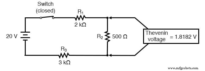
In this network the capacitor (C1 = 100 µF) is the load. We temporarily remove it to determine the Thevenin equivalent seen from its terminals.
Step 2 – Compute the Thevenin Voltage (Vth)
With the switch closed and no load present, the voltage at the capacitor terminals (node 2–node 3) equals the voltage across resistor R2. Calculations give:
Vth = 1.8182 V
Because a fully charged capacitor behaves as an open circuit (zero current), this is also the final steady‑state voltage the capacitor will reach.
Step 3 – Compute the Thevenin Resistance (Rth)
All independent sources are turned off (voltage sources shorted, current sources opened). The resulting resistance seen from the capacitor terminals is:
Rth = 454.545 Ω
Step 4 – Calculate the Time Constant
With C1 = 100 µF, the circuit’s time constant is:
τ = Rth · C1 = 454.545 Ω × 100 µF = 0.0454545 s (45.45 ms)
Step 5 – Determine the Transient Response
Assuming the capacitor starts uncharged (V0=0 V), the voltage at any time t is:
V(t) = Vth · (1 – e–t/τ)
At t = 60 ms:
V(60 ms) = 1.8182 V × (1 – e–0.06/0.0454545) ≈ 1.3325 V
Verification with SPICE Simulation
The following netlist was used to confirm the analytical result. The transient analysis samples every 5 ms over 370 ms.
* Original circuit
v1 1 0 dc 20
r1 1 2 2k
r2 2 3 500
r3 3 0 3k
c1 2 3 100u ic=0

* Thevenin equivalent
v2 4 0 dc 1.818182
r4 4 5 454.545
c2 5 0 100u ic=0

.tran 0.005 0.37 uic
.print tran v(2,3) v(5,0)
.end
The output shows identical capacitor voltages in both networks at every sampled instant, confirming the equivalence of the Thevenin reduction.
Review
- For any RC or RL network that is not a simple series configuration, treat the reactive element as the load.
- Reduce the remaining network to its Thevenin equivalent (one voltage source + series resistor).
- Apply the standard time‑constant formula to find the transient response.
Related Worksheets
Industrial Technology
- Advanced Motor Control Circuits: Latching, Stop, and Time‑Delay Techniques
- Complementary NPN/PNP Audio Amplifier Circuit – Direct Coupling for Moderate Power
- Understanding Simple Series Circuits: Key Principles and Practical Examples
- Redrawing Complex Circuit Schematics: A Step‑by‑Step Guide
- Fundamentals of AC Circuit Calculations: From Resistance to Kirchhoff’s Laws
- Series RC Circuit Analysis: Impedance, Phase Relationships, and SPICE Validation
- Parallel Resistor–Capacitor AC Circuits: Analysis, Impedance, and Ohm’s Law
- Impact of Resistance on Resonance in Series‑Parallel LC Circuits
- Inside the Manufacturing of Electronic Circuits
- Integrated Circuits Explained: A Complete Guide for Engineers