


Redrawing Complex Circuit Schematics: A Step‑by‑Step Guide
In practice, many real‑world circuit diagrams are cluttered and difficult to parse. This section presents a systematic approach that transforms a tangled layout into a clean, vertically‑aligned schematic, making series and parallel relationships immediately apparent.
Analyzing and Simplifying a Complex Circuit Diagram
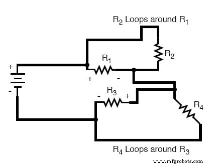
Let’s start with the following convoluted circuit diagram. It may have been drawn by a technician, or sketched from a physical layout. Regardless of its origins, the diagram’s current state can be hard to read:
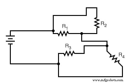
Wire routing in a schematic is largely a visual convenience; it rarely affects circuit behavior. In most DC applications, length changes have negligible impact, although in high‑frequency AC circuits very long traces can introduce unwanted resistance and phase shifts.
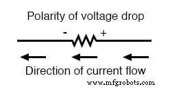
The most intuitive way to untangle a messy diagram is to follow the current path from one battery terminal to the other, tracing a single loop. While moving along this loop, annotate each resistor with the voltage‑drop polarity that a conventional‑current model would predict: positive at the entering side, negative at the exit.
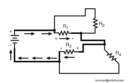
For this example, we begin at the battery’s positive terminal and proceed to the negative terminal, mirroring the natural direction of current flow. The resulting annotations look like this:
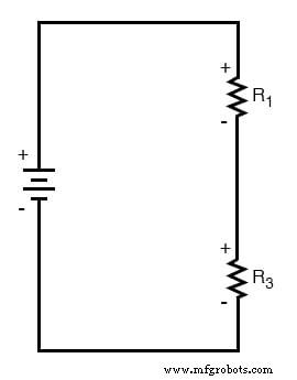
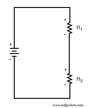
Every component encountered along this initial loop is drawn vertically in the order it appears:
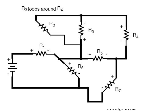
Next, we trace any additional loops that branch off the components already mapped. In this circuit, a loop surrounds resistor R₁ via R₂, and another loop surrounds R₃ via R₄:
By adding these loops, R₂ and R₄ are positioned in parallel with R₁ and R₃, respectively, in the vertical diagram. Their polarity markers match those of the original resistors:
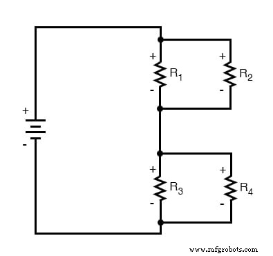
The resulting schematic is far easier to interpret and mirrors the classic four‑resistor series‑parallel configuration discussed earlier in the chapter.
Another Example for Simplification of Complex Circuits
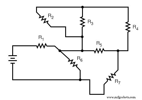
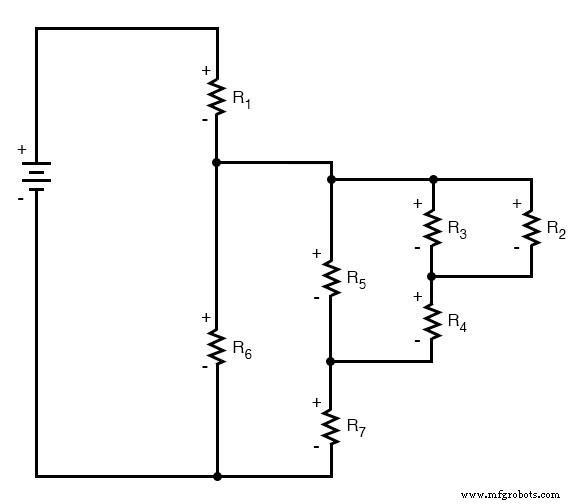
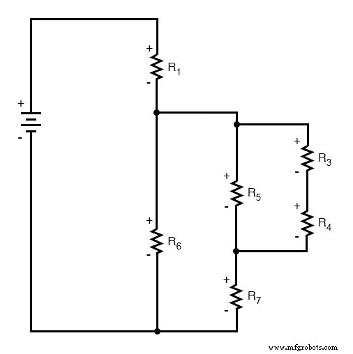
Consider an even more tangled diagram:
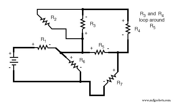
We start by tracing a loop that begins at the battery’s negative terminal, passes through R₆, then R₁, and returns to the positive terminal:
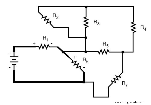
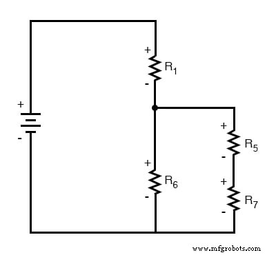
Drawing this loop vertically and noting voltage‑drop polarities yields the initial simplified view:
We then follow the loop that surrounds R₆, comprising R₅ and R₇. Starting at R₆’s positive side, we annotate the polarities as we move to its negative side:
Adding this loop to the vertical schematic, we observe that the polarities of R₇ and R₅ align with those of R₆, confirming the consistency of our tracing:
Continuing the process, we trace the R₃‑R₄ loop that surrounds R₅:
Incorporating this loop into the vertical diagram, with correct polarity markers, gives:
Only R₂ remains untraced. We therefore add the loop that encloses R₂ around R₃:
Integrating R₂ completes the clean schematic:
This ordered layout simplifies the reduction of the entire network to a single equivalent resistance. Starting from the right, we first combine R₂ and R₃ in parallel, then add R₄ in series, and so on, following the conventional reduction sequence until a single resistance value is obtained. From that point, the total current (I = E / R) and voltage distributions across each resistor can be calculated and then mapped back onto the original diagram.
Review
- Wire length and routing are visual conveniences; they do not alter circuit behavior in most cases.
- To simplify a tangled schematic, follow these steps:
- Trace a single current loop from one battery terminal to the other, marking voltage‑drop polarities for each resistor.
- Draw the traced components vertically, then identify and trace any additional loops that branch off those components, using polarity markers to guide placement.
- Repeat until every component in the original diagram has been mapped.
Related Worksheets
- Algebraic Substitution for Electric Circuits Worksheet
- Series‑Parallel DC Circuits Worksheet
Industrial Technology
- Circuit With a Switch: A Practical Guide to Basic Electrical Circuits
- Voltage Follower Amplifier: Design, Build, and Measurement Guide
- Mastering AC Circuit Equations: Impedance, Reactance & Resonance
- Getting Started with SPICE: A Text‑Based Circuit Simulation Tool
- Mastering SPICE Netlist Syntax: Component Naming, Passive & Active Elements, and Source Definitions
- Demultiplexers Explained: How They Route Signals in Digital Circuits
- Understanding TRIACs: Bidirectional Power Control in AC Applications
- Understanding Electrical Resistance and Circuit Safety
- Analyzing Complex RC Circuits Using Thevenin’s Theorem
- Electro Schematics: Why They’re Essential for Reliable Circuit Design