


Voltage Follower Amplifier: Design, Build, and Measurement Guide
PARTS AND MATERIALS
- One NPN transistor – models 2N2222 or 2N3403 are recommended. A 15‑piece pack (Radio Shack catalog # 276‑1617) is ideal for this and other projects.
- Two 6‑volt batteries
- Two 1 kΩ resistors
- One 10 kΩ single‑turn linear potentiometer (Radio Shack catalog # 271‑1715)
Transistor pinouts vary even among visually identical packages. Always consult the manufacturer’s datasheet before wiring. A quick verification with a multimeter’s diode‑check function is highly advisable.
For a step‑by‑step guide on identifying bipolar transistor terminals with a multimeter, see chapter 4 of the Semiconductor Volume III series.
CROSS‑REFERENCES
Lessons In Electric Circuits, Volume 3, chapter 4: “Bipolar Junction Transistors.”
LEARNING OBJECTIVES
- Understand the role of circuit “ground” when no earth connection exists.
- Use a shunt resistor to measure current with a voltmeter.
- Determine amplifier voltage gain.
- Determine amplifier current gain.
- Explore impedance transformation in an amplifier.
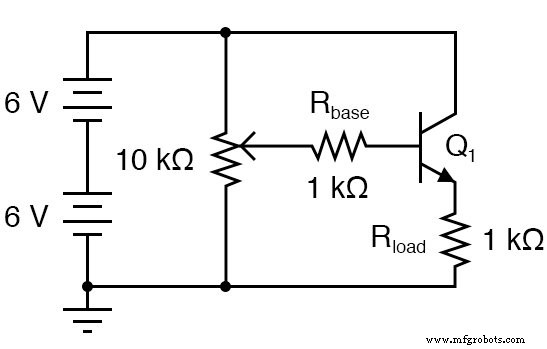
SCHEMATIC DIAGRAM
ILLUSTRATION
INSTRUCTIONS
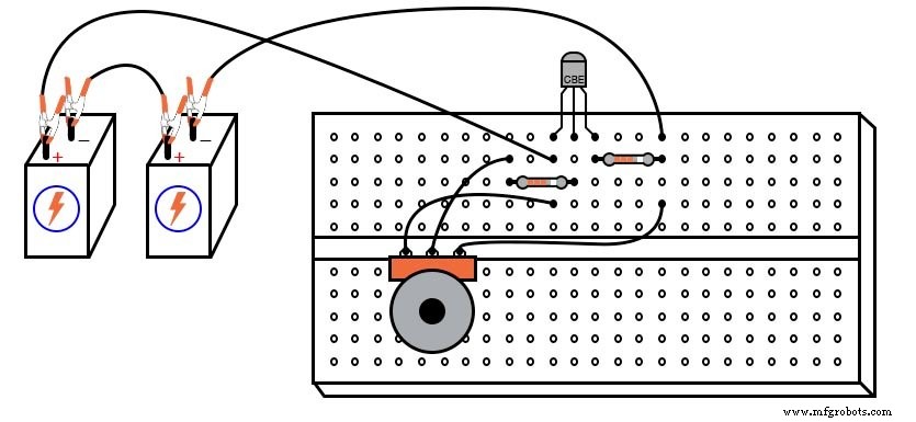
Because the transistor chosen may not share the pinout shown here, the breadboard layout in the illustration might need adjustment. In the figures, all TO‑92 transistors are labeled “CBE” – Collector, Base, Emitter – from left to right. This applies to the 2N2222 and similar parts, but not to every NPN device. Verify pin assignments for the specific component you use.
With bipolar junction transistors, a multimeter can quickly confirm pinouts. The voltage follower is the simplest and safest transistor amplifier to construct.
Its purpose is to deliver the same voltage to a load as the input, but with significantly higher current capability. It has no voltage gain, yet it offers substantial current gain.
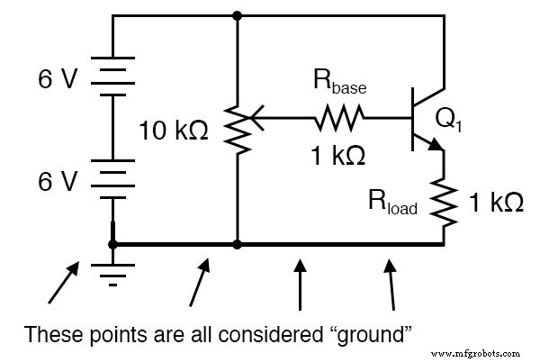
In the schematic, the negative terminal of the power supply is marked as “ground.” This reference point is not necessarily connected to earth; it merely defines the voltage baseline for the circuit.
For example, the base voltage (VB) is measured relative to this ground reference. While speaking of voltage “at” a single point is normally meaningless, a common reference point makes such statements useful.
Build the circuit and record the output voltage versus input voltage for several potentiometer settings. Input voltage is the voltage at the potentiometer wiper relative to ground; output voltage is the voltage across the load resistor (or emitter voltage).
You should observe a close correlation: a change in input produces an almost equal change in output, with a small drop (~0.6 V) due to transistor saturation. This 1:1 relationship indicates an AC voltage gain of approximately unity.
Next, compare base current (input) with load current (output). Rather than inserting an ammeter, measure the voltage across the 1 kΩ resistors and use Ohm’s law (I = E/R). With 1 kΩ resistors, 1 mA flows per volt of drop.
For maximum accuracy, measure each resistor’s actual value, though variations are typically negligible for this experiment. These shunt resistors convert current into a measurable voltage.
You will find a large disparity between input and output currents – current gains often exceed 200 at low signal levels. This is the voltage follower’s core advantage: it amplifies current without altering voltage.
In impedance terms, the amplifier presents high input impedance (minimal current draw) and low output impedance (capable of delivering high current). This makes it ideal for buffering signals between stages.
COMPUTER SIMULATION
Schematic with SPICE node numbers:
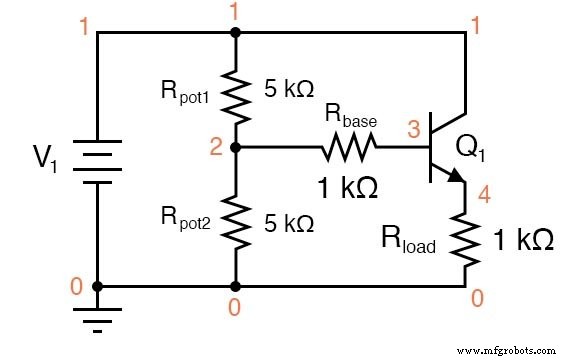
Netlist (copy the following text into a .cir file and run with SPICE):
Voltage follower v1 1 0 rpot1 1 2 5k rpot2 2 0 5k rbase 2 3 1k rload 4 0 1k q1 1 3 4 mod1 .model mod1 npn bf=200 .dc v1 12 12 1 .print dc v(2,0) v(4,0) v(2,3) .end
The simulation outputs an input voltage of 5.937 V and an output of 5.095 V, with an input current of 25.35 µA (from a 1 kΩ base resistor) and an output current of 5.095 mA (from the 1 kΩ load). Adjusting the potentiometer values (Rpot1 and Rpot2) while keeping their sum at 10 kΩ changes the input voltage accordingly.
RELATED WORKSHEET:
- Bipolar Transistor Biasing Circuits Worksheet
Industrial Technology
- Build a Low‑Frequency Astable Multivibrator Audio Oscillator with Discrete Transistors
- Precision Voltage Follower: Mastering Op‑Amp Feedback for Accurate Signal Tracking
- Essential DC Circuit Equations and Laws for Engineers
- Mastering AC Circuit Equations: Impedance, Reactance & Resonance
- From Vacuum Tubes to Integrated Circuits: The Evolution of Operational Amplifier Models
- Analyzing Circuit Response to Multi‑Frequency Sources
- Build a Voltage Tripler Circuit: Step‑by‑Step Guide
- LM7805 Voltage Regulator Circuit: Complete Overview & Practical Guide
- Understanding Voltage Monitoring Circuits: A Practical Guide
- Understanding Reverse Voltage: Causes, Effects, and Safety Tips