


Build a Low‑Frequency Astable Multivibrator Audio Oscillator with Discrete Transistors
PARTS AND MATERIALS
- Two 6‑volt batteries
- Three NPN transistors (2N2222 or 2N3403 recommended; Radio Shack catalog # 276‑1617 contains a convenient 15‑pack)
- Two 0.1 µF capacitors (Radio Shack catalog # 272‑135 or equivalent)
- One 1 MΩ resistor
- Two 100 kΩ resistors
- One 1 kΩ resistor
- Assorted resistor pairs below 100 kΩ (e.g., two 10 kΩ, two 5 kΩ, two 1 kΩ)
- One LED (Radio Shack catalog # 276‑026 or equivalent)
- Audio detector with headphones
CROSS‑REFERENCES Lessons In Electric Circuits, Vol. 3, Ch. 4: “Bipolar Junction Transistors”; Vol. 4, Ch. 10: “Multivibrators”
LEARNING OBJECTIVES
- Construct an astable multivibrator using discrete transistors and understand its frequency‑determining parameters.
SCHEMATIC DIAGRAM
ILLUSTRATION
INSTRUCTIONS
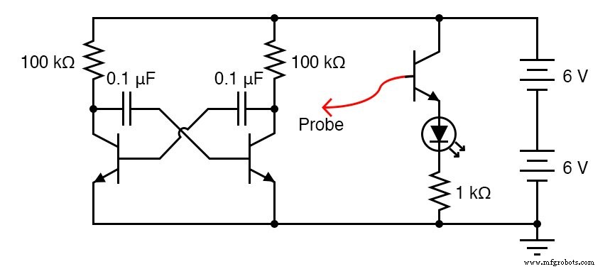
The circuit in question is an astable multivibrator, a free‑running oscillator whose timing is set by the values of the resistors, capacitors, and the supply voltage. While the output waveform is neither a clean sine nor a perfect square, the distortion is negligible for generating an audible tone.
With a 12‑V supply, 100 kΩ resistors, and 0.1 µF capacitors, the oscillator produces a low‑audio frequency that can be heard through an audio detector. For best results, connect one probe to ground and the other to the collector of one of the switching transistors.
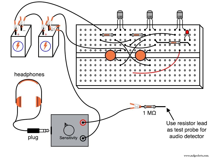
Place a 1 MΩ series resistor across the audio detector to reduce loading on the multivibrator and to keep headphone volume at a comfortable level:
The core of the multivibrator consists of two transistors, two resistors, and two cross‑connected capacitors. The third transistor in the schematic powers an LED that visually confirms oscillation.
Use a probe on the base of the common‑emitter amplifier to observe voltage variations at different nodes. With the probe on the collector of either switching transistor, you’ll see the LED blink at the oscillator’s frequency. If you probe the base of a switching transistor, the LED won’t light because the base voltage (≈0.7 V) is below the LED’s forward‑bias threshold, even though the audio detector will still pick up the low‑level signal.
Experiment with lower‑value resistors in place of the 100 kΩ pair and observe the resulting shift in oscillation frequency. Typically, resistors of at least 1 kΩ are used to keep transistor currents within safe limits.
Many oscillators require a minimum supply voltage; if the voltage is too low, the circuit will not start. Try reducing the supply voltage gradually to determine the threshold for oscillation and note how the frequency changes with voltage.
Oscillation initiation can be sensitive to component mismatches. One transistor must turn on before the other to start the cycle. If the circuit “freezes” at power‑up, swap out components of the same value to introduce fresh tolerances and restore activity.
RELATED WORKSHEET
- Oscillator Circuits Worksheet
Industrial Technology
- Voltage Follower Amplifier: Design, Build, and Measurement Guide
- DIY 12AX7 Vacuum Tube Audio Amplifier – Classic Sound Build
- 555 Timer Astable Oscillator: LED Demo & Duty Cycle Exploration
- Essential DC Circuit Equations and Laws for Engineers
- From Vacuum Tubes to Integrated Circuits: The Evolution of Operational Amplifier Models
- Analyzing Circuit Response to Multi‑Frequency Sources
- Build a Voltage Tripler Circuit: Step‑by‑Step Guide
- How to Build an Audio Mixer: 5 Practical Methods
- LM7805 Voltage Regulator Circuit: Complete Overview & Practical Guide
- Understanding Reverse Voltage: Causes, Effects, and Safety Tips