


Analyzing Circuit Response to Multi‑Frequency Sources
The principle that any periodic, non‑sinusoidal waveform can be decomposed into a set of sine waves of different frequencies is foundational in AC circuit analysis.
When a circuit is driven by a waveform that is not a pure sine, the elements in the circuit respond as if a spectrum of frequency components were applied simultaneously.
Reactive components—capacitors and inductors—exhibit a distinct impedance for each frequency present, so the overall response depends on the full frequency spectrum of the source.
To analyze such situations, engineers rely on the Superposition Theorem. By treating a multi‑frequency source as a series of single‑frequency voltage sources, we can solve the circuit for one frequency at a time and then combine the results to obtain the total response.
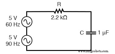
Example: Circuit powered by 60 Hz and 90 Hz components
First, solve for the 60 Hz component:
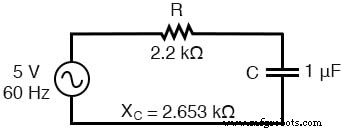
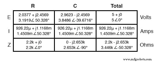
Analysis of the 60 Hz branch
Next, solve for the 90 Hz component:
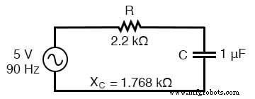
Analysis of the 90 Hz branch
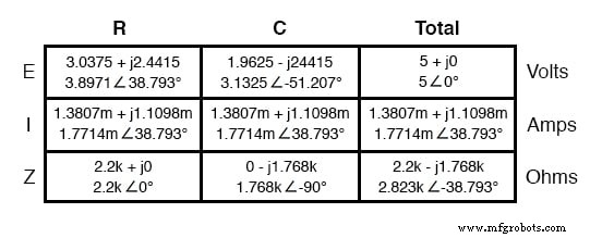
By superimposing the voltage drops across the resistor and capacitor, we obtain:
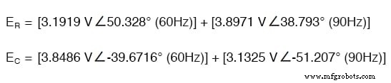
Because the voltage across each element contains different frequency components, we cannot simply add them as if they shared the same frequency. Complex numbers capture magnitude and phase but not frequency, so each component must be treated separately.
The analysis reveals that the capacitor experiences a larger voltage drop at 60 Hz than at 90 Hz, while the resistor exhibits the opposite behavior—even though the two source voltages are equal in amplitude. This unequal response to different frequencies is a key concept explored in depth in the next chapter.
Superposition also applies to non‑sinusoidal sources such as square waves. By expressing the waveform as a Fourier series—a sum of sine and cosine terms at odd harmonics—we can treat it as a chain of sinusoidal sources with specific amplitudes, frequencies, and phase shifts.
Although the Fourier series for a square wave requires many terms (the standard series extends to the ninth harmonic for good accuracy), the approach remains valid. The complexity is the trade‑off for a precise representation of the waveform.
In practice, a real‑world circuit powered by a square wave behaves exactly as if it were powered by an infinite series of odd‑harmonic sine waves with decreasing amplitudes. This can lead to resonant peaks, core heating in transformers and inductors, broadband electromagnetic noise, and other unintended effects. Engineers must therefore account for non‑sinusoidal waveforms when designing reactive circuits.
Harmonics also manifest as electromagnetic radiation. Studies on the use of portable computers in passenger aircraft have shown that the high‑frequency square‑wave clock signals can generate radio waves that interfere with avionics. Because the harmonics of a clock signal spread across a wide frequency range, the potential for interference is significant.
Industrial settings face similar challenges. The shift from mechanical to solid‑state motor controls has introduced high‑frequency harmonics that couple capacitively and inductively to nearby signal wiring, producing noise that was absent with older, purely resistive controls.
While the fundamental power line frequency is 60 Hz, its harmonics theoretically extend to arbitrarily high frequencies. Low‑frequency power lines emit little electromagnetic energy, but higher frequencies radiate more efficiently. Coupling between conductors is also more pronounced at high frequencies, making signal integrity a concern in modern electronic systems.
REVIEW
- Any periodic, non‑sinusoidal waveform can be represented as a Fourier series of sine/cosine components at various frequencies, phases, amplitudes, and a possible DC offset.
- Multiple‑frequency sources can be simulated by chaining single‑frequency voltage sources; the superposition theorem lets us analyze each frequency separately. Note that voltages or currents at different frequencies cannot be added in the complex‑number domain, as complex numbers do not encode frequency.
- Harmonics introduce unwanted “noise” into adjacent circuits through capacitive coupling, inductive coupling, and electromagnetic radiation.
RELATED WORKSHEETS
- Superposition Theorem Worksheet
Industrial Technology
- Voltage Follower Amplifier: Design, Build, and Measurement Guide
- Build a Low‑Frequency Astable Multivibrator Audio Oscillator with Discrete Transistors
- Essential DC Circuit Equations and Laws for Engineers
- Mastering AC Circuit Equations: Impedance, Reactance & Resonance
- From Vacuum Tubes to Integrated Circuits: The Evolution of Operational Amplifier Models
- Voltage and Current in a Practical Circuit: Understanding Their Relationship
- Build a Voltage Tripler Circuit: Step‑by‑Step Guide
- LM7805 Voltage Regulator Circuit: Complete Overview & Practical Guide
- Understanding Voltage Monitoring Circuits: A Practical Guide
- Understanding Reverse Voltage: Causes, Effects, and Safety Tips