


Potentiometric Voltmeter: Precise Voltage Measurement with Minimal Loading
Parts & Materials
- Two 6‑V batteries
- Single‑turn, 10 kΩ linear potentiometer (Radio Shack #271‑1715)
- Two high‑value resistors (≥1 MΩ each)
- Sensitive voltage detector (from the previous experiment)
- Analog voltmeter (from the previous experiment)
The potentiometer value is flexible—anywhere from 1 kΩ to 100 kΩ will work. If you’ve built the precision potentiometer described earlier in this chapter, it’s ideal for this exercise. Likewise, larger resistor values improve accuracy; they need not be identical.
If you haven’t yet constructed the sensitive voltage detector, we recommend doing so first. A homemade detector is inexpensive, yet demonstrates how to make precise voltage measurements without costly equipment. A digital multimeter set to the DC millivolt range can serve as a substitute, but a headphone‑based detector is preferable for learning purposes.
Cross‑References
Lessons In Electric Circuits, Volume 1, Chapter 8: "DC Metering Circuits"
Learning Objectives
- Understand voltmeter loading: its causes and how to mitigate it
- Use a potentiometer as a variable voltage source
- Apply the potentiometric (null‑balance) method for accurate voltage measurement
Schematic Diagram
Illustration
Instructions
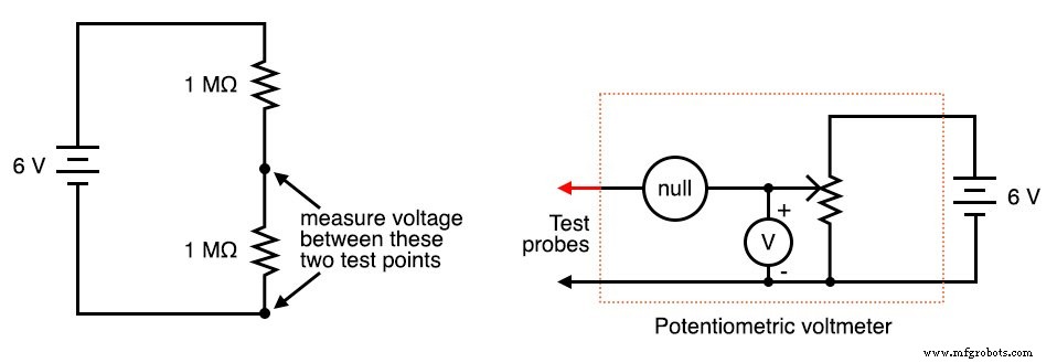
1. Assemble the two‑resistor voltage divider shown on the left side of the schematic.
2. If the high‑value resistors are equal, the 6‑V battery should split into two 3‑V drops.
3. Measure the battery voltage with a voltmeter, then measure the drop across each resistor.
You’ll likely notice a discrepancy: the sum of the individual drops does not equal the total battery voltage. This is not a violation of Kirchhoff’s Voltage Law; it’s a classic example of voltmeter loading.
Analogy: A tire gauge releases a small amount of air when connected, slightly lowering the tire pressure. Similarly, a voltmeter provides a path for current that slightly alters the voltage across the component it measures.
In this circuit the effect is pronounced because the test resistors are high‑value. Replace them with 100 kΩ units, then with 10 kΩ units, and observe how the voltage readings change. Lower resistance reduces the loading impact, but at the cost of measurement accuracy.
Try measuring each resistor with a digital voltmeter instead of an analog one. Digital meters typically have higher input impedance (often >10 MΩ), so they draw less current and produce readings closer to the true voltage.
For a more accurate approach, use the potentiometric (null‑balance) method. This technique balances the test voltage against an adjustable voltage source (the potentiometer) and uses a highly sensitive null detector to indicate balance. Once balanced, the potentiometer’s voltage—read with a voltmeter—equals the test voltage, free from loading errors.
Potentiometric Voltmeter Circuit
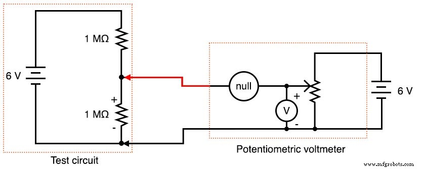
The circle labeled "null" represents the null detector. Any sensitive meter movement or voltage indicator can serve as the detector; its role is solely to signal zero voltage difference.
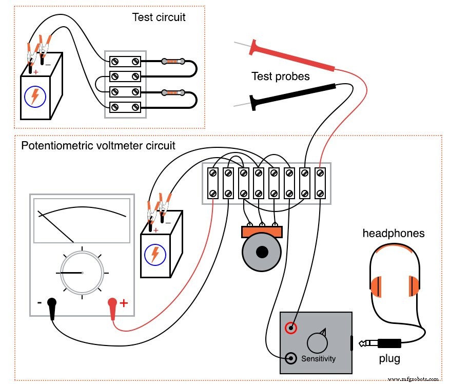
Build the circuit as illustrated and use it to measure the voltage drop across one of the high‑value resistors. Initially, a regular multimeter can function as the null detector while you become familiar with the process. If you prefer the headphone‑based detector, make brief contact with each test point and listen for the characteristic clicking that fades to silence at balance.
Note: A single‑turn potentiometer may be too coarse for precise nulling. Consider a multi‑turn unit or the precision potentiometer circuit described earlier.
Computer Simulation
SPICE schematic with node numbers:
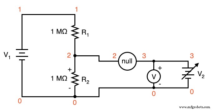
Netlist (copy the following into a text file named potentiometric.cir):
Potentiometric voltmeter v1 1 0 dc 6 v2 3 0 r1 1 2 1meg r2 2 0 1meg rnull 2 3 10k rmeter 3 0 50k
.dc v2 0 6 0.5
.print dc v(2,0) v(2,3) v(3,0)
.end
The simulation demonstrates that the test voltage is only accurate when the null detector reads zero—i.e., when the potentiometer is perfectly balanced. At that point, the adjustable source reads exactly 3.000 V, matching the true voltage drop across the test resistor.
Related Worksheets
- DC Metrology Worksheet
Industrial Technology
- Mastering Voltmeter Use: Accurate Voltage Measurement Made Simple
- Exploring Voltage Addition with Series Battery Connections
- Voltage Divider Lab: Design, Measurement, and Kirchhoff’s Voltage Law Verification
- Thermoelectricity: Understanding Thermocouples and the Seebeck Effect
- Build a Potato Battery: A Step‑by‑Step Guide to DIY Electrochemical Power
- Low‑Voltage AC Power Supply: Phase‑Shift Circuit Components & Best Practices
- Voltage Regulator Experiment with a 12‑Volt Zener Diode
- Tachogenerators: Precision Speed Measurement for Industrial Motors and Equipment
- Understanding AC Waveforms: Sine Waves, Frequency, and Oscilloscope Basics
- Voltmeter IC: Precision Voltage Measurement Made Simple