


Sensitive Voltage Detector: Build a High‑Sensitivity Audio Signal Detector
PARTS AND MATERIALS
- High‑quality closed‑cup audio headphones
- Female headphone jack (Radio Shack #274-312)
- Small step‑down power transformer (Radio Shack #273-1365 or equivalent; use the 6 V secondary tap)
- Two 1N4001 rectifying diodes (Radio Shack #276-1101)
- 1 kΩ resistor
- 100 kΩ potentiometer (Radio Shack #271-092)
- Two banana‑jack binding posts (Radio Shack #274-662 or equivalent)
- Plastic or metal mounting box
Headphone sensitivity is critical. The higher the dB rating, the better the detector. Test several models at a reputable audio shop; the model that audibly responds to the lowest volume on a radio or CD player is ideal. You don’t need the most expensive pair—an older Radio Shack “Realistic” set has worked well in practice.
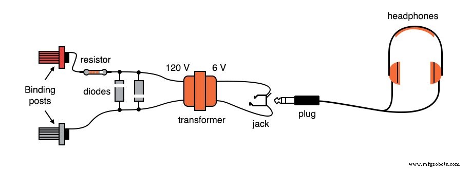
A transformer is employed to convert the low‑voltage input into a form that drives the headphones. A small step‑down power transformer (120 V → 6 V) is inexpensive, rugged, and provides the impedance matching needed for low‑current signals.
The 1 kΩ resistor’s tolerance is unimportant; it simply limits the voltage across the transformer’s primary. The 100 kΩ potentiometer allows the user to adjust loudness and attenuate stronger signals.
Although an audio‑taper potentiometer would be ideal, a linear taper works equally well for this application.
CROSS‑REFERENCES
- Lessons In Electric Circuits, Vol 1, ch 8: “DC Metering Circuits”
- Lessons In Electric Circuits, Vol 1, ch 10: “DC Network Analysis” (Maximum Power Transfer Theorem)
- Lessons In Electric Circuits, Vol 2, ch 9: “Transformers”
- Lessons In Electric Circuits, Vol 2, ch 12: “AC Metering Circuits”
LEARNING OBJECTIVES
- Practice soldering techniques
- Detect extremely small electrical signals
- Use a potentiometer as a voltage divider / signal attenuator
- Employ diodes to clip voltage at a maximum level
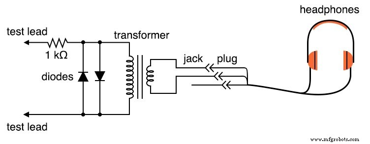
SCHEMATIC DIAGRAM
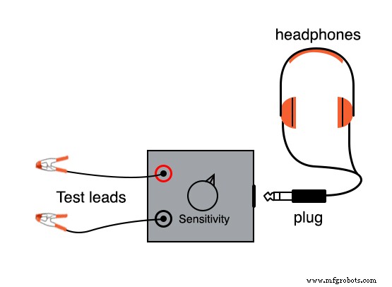
ILLUSTRATIONS
INSTRUCTIONS
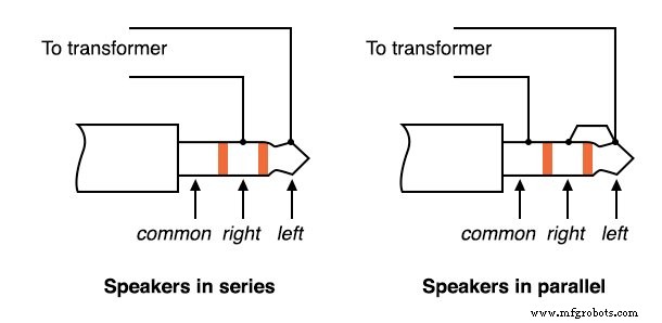
Most headphones are stereo with a three‑contact plug; you will connect only two contacts. If you have a mono set, use its two contacts.
Connect the left and right drivers in series—this maximizes the audible response to a small signal.
Solder all connections cleanly. Loose contacts add noise and can mask the faint signals the detector is designed to hear.
The two 1N4001 diodes and the 1 kΩ resistor are wired across the transformer’s primary. They limit the voltage drop to about 0.7 V, preventing excessive sound that could damage headphones or create a hazardous noise level if the detector is connected to a high‑voltage source.
Banana‑jack binding posts mount the test leads. Use standard multimeter probes or alligator clips for secure connection.
The detector is suited for bridge balance, null‑balance voltmeters, and detecting low‑amplitude AC signals in the audio band—an inexpensive alternative to an oscilloscope.
When testing sources above 1 V, attenuate the signal by placing a voltage divider at the front of the circuit.
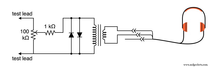
Adjust the 100 kΩ potentiometer to mid‑range as a starting point. Increase the knob if the sound is too quiet, or decrease it if the sound is too loud.
The detector clicks whenever the test leads connect or disconnect from a voltage source. With low‑cost headphones, it can detect currents below 0.1 µA. A simple test is to touch the leads to the tip of your tongue; the galvanic voltage from the wet skin produces a faint clicking sound.
Because headphones are low‑impedance devices (≈8 Ω), they require low voltage but high current to produce sound. The transformer matches the high‑impedance source to the headphone, maximizing power transfer per the Maximum Power Transfer Theorem and producing a magnetic “kickback” that amplifies even tiny DC signals.
For long‑term use, mount all components in a plastic or metal box and run dedicated test lead wires. This permanent build makes the detector ready for future experiments.
RELATED WORKSHEETS
- Design Project: Sensitive Audio Detector Worksheet
Industrial Technology
- High‑Sensitivity Audio Detector for Ultra‑Low Electrical Signals
- Using Commutating Diodes to Protect Inductive Loads
- Passive Averager and Op‑Amp Summer Circuits: From Averaging to Addition
- Power Supply Circuits: Types, Design Principles, and Performance
- Crystal and Transistor Radio Circuits: From Basic Detectors to Integrated AM/FM Receivers
- Understanding Power in Electric Circuits: Measurement & Significance
- Voltage Divider Circuits: Mastering Series Resistor Analysis & Potentiometers
- Illustrating AC Voltage Addition Using Complex Numbers
- Understanding AC Inductor Circuits: Reactance, Phase Shift, and Power Dynamics
- AC Capacitor Circuits: Capacitive Reactance, Phase Shift, and Power Behavior