


Crystal and Transistor Radio Circuits: From Basic Detectors to Integrated AM/FM Receivers
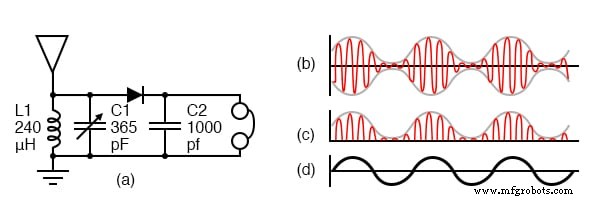
The core of a crystal radio consists of an antenna, a ground connection, a tank circuit (C1 and L1), a peak detector, and headphones. The antenna captures broadcast signals (b), which travel through the circuit to ground. The tank circuit, a resonant LC pair, selects a single station from the spectrum; C1 is variable to enable tuning. A germanium diode rectifies the radio frequency (RF) by allowing only the positive half‑cycles to pass, producing the RF envelope (c). The filtering capacitor C2 removes the remaining RF component, leaving only the audio frequency (d) that drives the headphones.
Crystal radios operate without any external power supply. A germanium diode is preferred over silicon because its lower forward voltage drop (~0.2 V) offers greater sensitivity, especially for weak signals. If a silicon diode is used, the circuit will still function, though with reduced performance.
While the schematic shows 2000 Ω magnetic headphones, a ceramic “crystal” earphone offers higher sensitivity and is the preferred choice for most signals. Magnetic headphones can be substituted with low‑impedance earbuds when paired with an appropriate audio transformer.
Below is a stronger variant that replaces the crystal detector with a transistor. The germanium PNP transistor is biased to conduct only during the positive half‑cycles of the RF input, thus acting as a detector with built‑in amplification. This configuration produces a louder output capable of driving 2000 Ω headphones directly. A silicon NPN transistor will also work if the base‑bias resistor is adjusted accordingly.
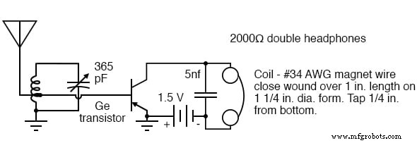
Modern low‑impedance earbuds can replace the original 2000 Ω headphones, provided they are matched with an audio transformer or a suitable amplifier.
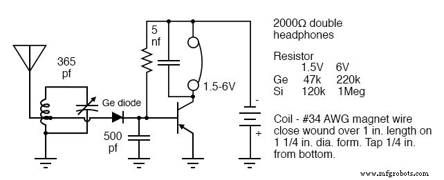
The following schematic adds an audio amplifier stage to the crystal detector, further increasing headphone volume. The original design uses a germanium diode and transistor; a Schottky diode may replace the germanium diode, and a silicon transistor can be used if the base‑bias resistor is modified as per the accompanying table.
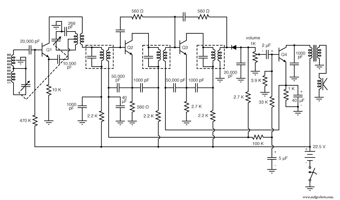
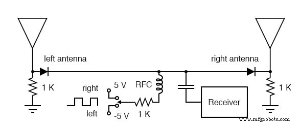
For a broader perspective on crystal radio designs, simple one‑transistor radios, and advanced low‑transistor configurations, see the examples below.
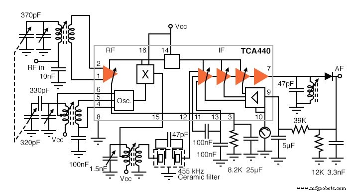
The integrated‑circuit (IC) AM radio consolidates all active RF components into a single IC, with only a few external capacitors, inductors, and resistors. A 370 pF variable capacitor tunes the RF input, while a 320 pF capacitor adjusts the local oscillator 455 kHz above the RF. The mixing occurs at pin 15, producing sum and difference frequencies; a 455 kHz ceramic filter selects the desired difference. Most of the amplification takes place in the intermediate frequency (IF) stage between pins 12 and 7, with a diode at pin 7 recovering the audio. Automatic gain control (AGC) is derived from pin 9.
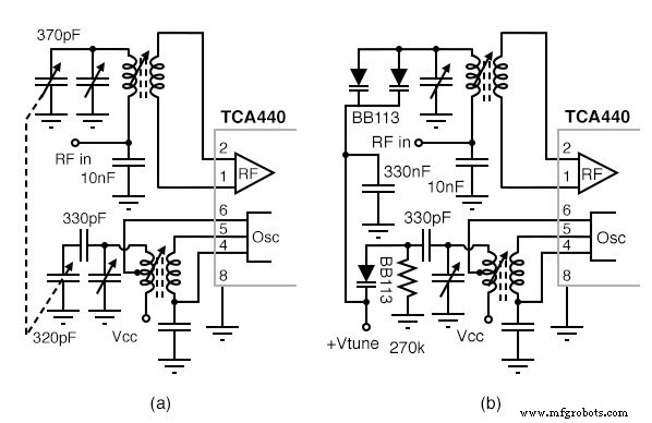
Mechanical tuning of the RF tuner and local oscillator, as shown in (a), can be replaced with electronic varicap diode tuning in (b). Using a varicap diode reduces component bulk; increasing the reverse bias voltage decreases capacitance, raising the tuning frequency. The bias voltage can be generated by a potentiometer.
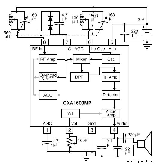
A further reduction in parts count is achieved when the IF band‑pass filter is integrated into the IC, eliminating external IF transformers and ceramic filters. The RF input and local oscillator still require L‑C tuning, which can again be replaced by varicap diodes if desired.
For FM reception, a TDA7021T IC from NXP Wireless offers a low‑parts‑count solution. External IF transformers are replaced by RC filters; the IC supplies the necessary resistors while capacitors remain external. The simplified tuning circuit mirrors Figure 5 in the NXP datasheet, and a more elaborate tuner can be found in Figure 8. A stereo FM version includes an audio amplifier capable of driving a speaker.
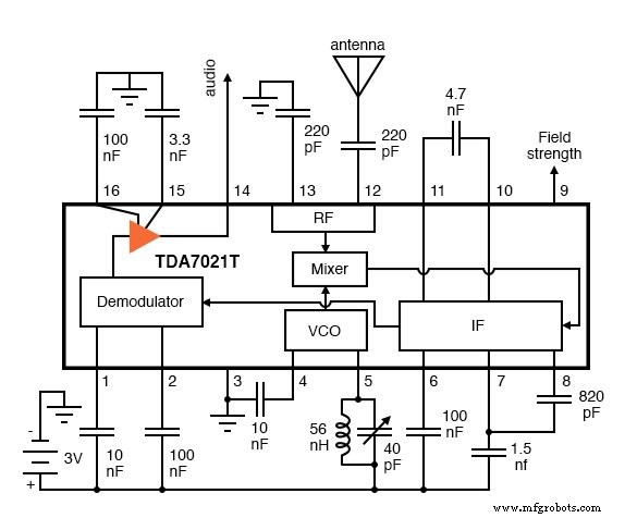
For hobbyists building this FM radio, the 56 nH inductor can be wound with eight turns of #22 AWG bare or magnet wire on a 0.125‑inch mandrel, then stretched to 0.6 inches. A miniature trimmer capacitor serves as the tuning element.
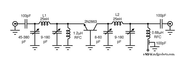
The following schematic demonstrates a common‑base (CB) RF amplifier. Because it lacks a bias network, it operates as a class‑C amplifier, conducting for less than 180° of the input waveform. The CB configuration offers higher power gain at high RF frequencies than a common‑emitter design. With matching π‑networks at both input and output, the circuit achieves 50 Ω termination and filters out harmonics. For modern radiated‑emission standards, additional filtering sections may be necessary.
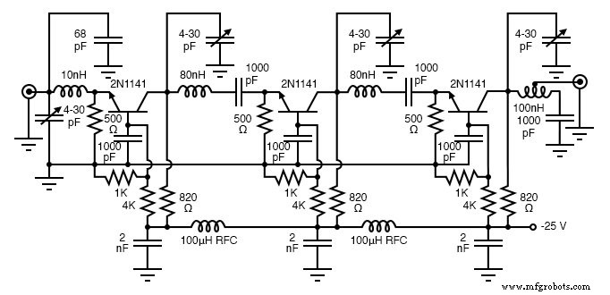
An even higher‑gain CB amplifier is shown below. With 1 kΩ–4 kΩ voltage dividers and 500 Ω emitter bias resistors, the transistor operates in class A. The configuration achieves 38 dB gain at 100 MHz with a 9 MHz bandwidth.
Combining a common‑emitter input stage with a common‑base output stage yields a cascode amplifier that offers both high bandwidth and moderate input impedance. The biasing network, detailed in Chapter 4 of the BJT text, is illustrated below.
Simulations of the cascode amplifier can be found in the “Cascode” section of the BJT chapter. For best high‑frequency performance, use RF or microwave transistors.
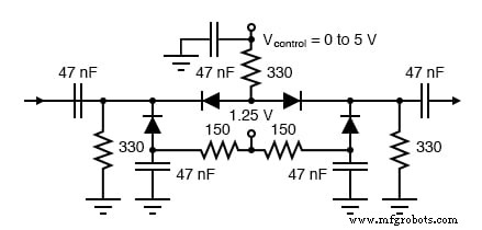
The PIN diodes form a π‑attenuator network. Anti‑series diodes reduce harmonic distortion compared to a single series diode. A fixed 1.25 V supply forward‑biases the parallel diodes, providing DC current and RF conduction through their junction capacitances. By varying the control voltage (Vcontrol), the resistance can be tuned from 80 dB attenuation at 10 MHz (Vcontrol = 0.5 V) to 3 dB at 5 V, with a flat response up to 2 GHz.
RELATED WORKSHEET:
- Fundamentals of Radio Communication Worksheet
Industrial Technology
- Foundations of DC Circuits: Understanding Direct Current and Core Electrical Concepts
- Sensitive Voltage Detector: Build a High‑Sensitivity Audio Signal Detector
- Understanding AC Circuits: A Beginner's Guide
- Rectifier Circuits: From Half‑Wave to Polyphase Full‑Wave Designs
- Understanding Clipper Circuits: Theory, Simulation, and Practical Applications
- Clamper Circuits – DC Restorers for Composite Video
- Analog vs. Digital Computational Circuits: A Practical Guide
- Control Circuits: Fundamentals, Applications, and Best Practices
- The Evolution and Engineering of Radio Technology
- Build a Reliable FM Radio with SparkFun & Arduino Components