


Rectifier Circuits: From Half‑Wave to Polyphase Full‑Wave Designs
What is Rectification?
Rectification is the conversion of alternating current (AC) into direct current (DC) using devices that permit current to flow in only one direction. The semiconductor diode is the most common element that performs this function in modern power supplies.
Half‑Wave Rectification
In a half‑wave rectifier only one half of each AC cycle reaches the load, producing a pulsating DC signal with significant harmonic content. This simple topology is useful for low‑power or illustrative applications, such as a two‑position lamp dimmer that delivers full AC power in the “full” setting and half‑wave‑rectified power in the “dim” setting (see figure).
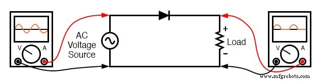
During the “dim” position, the incandescent filament receives roughly half the power it would under full AC. Because the filament’s thermal time constant is large, the rapid pulses of power do not cause visible flicker; instead the filament operates at a lower steady‑state temperature, yielding reduced light output.
Full‑Wave Rectifiers
Full‑wave rectifiers capture both halves of the AC cycle, delivering a smoother DC waveform. Two common configurations are the center‑tap and bridge designs.
Center‑Tap Design
Using a transformer with a center‑tapped secondary and two diodes, each half of the secondary drives the load during alternating half‑cycles (see figure). This topology requires a dedicated center‑tapped transformer, which can be costly for high‑power applications.
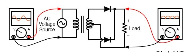
During the positive half‑cycle, the upper diode conducts and the lower blocks; during the negative half‑cycle, the roles reverse. In both cases the load sees a positive‑polarity waveform.
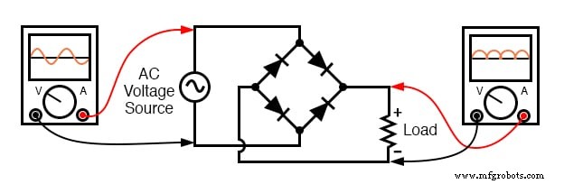
Bridge Design
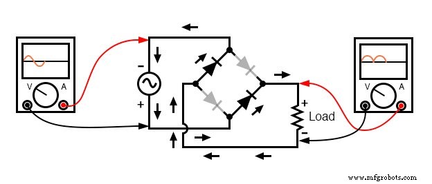
The four‑diode bridge eliminates the need for a center‑tapped transformer. Current flows through two diodes in series for each polarity, resulting in a 1.4 V drop for silicon diodes—a drawback at very low output voltages.
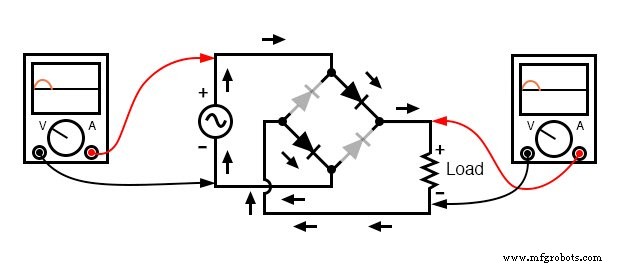
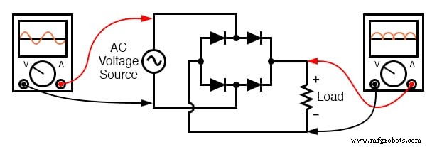
Diode current directions for the positive and negative halves of the input are shown below.
For better mnemonic recall, an alternative layout depicts all diodes in a horizontal orientation, all pointing the same way.
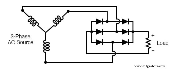
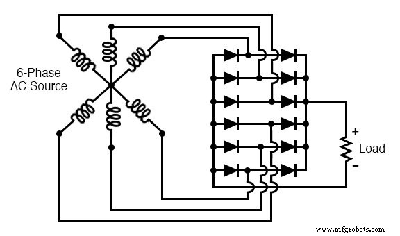
Polyphase Full‑Wave Bridge Rectifiers
Expanding the bridge concept to polyphase supplies yields smoother DC output because phase‑shifted pulses overlap. A three‑phase bridge produces six pulses per AC cycle; a six‑phase bridge produces twelve pulses, significantly reducing ripple voltage.
Ripple Voltage
All rectifiers produce some AC component—called ripple voltage—superimposed on the DC output. In high‑power or precision applications, filtering networks are employed to suppress this ripple.
Pulsing Conventions
Rectifiers are often described by the number of DC pulses they generate per electrical rotation: 1‑pulse (half‑wave), 2‑pulse (full‑wave), 6‑pulse (three‑phase full‑wave), and so forth. The standard notation 1Ph1W1P, 1Ph1W2P, 1Ph2W2P, 3Ph2W6P, etc., succinctly captures phase, current direction, and pulse count.
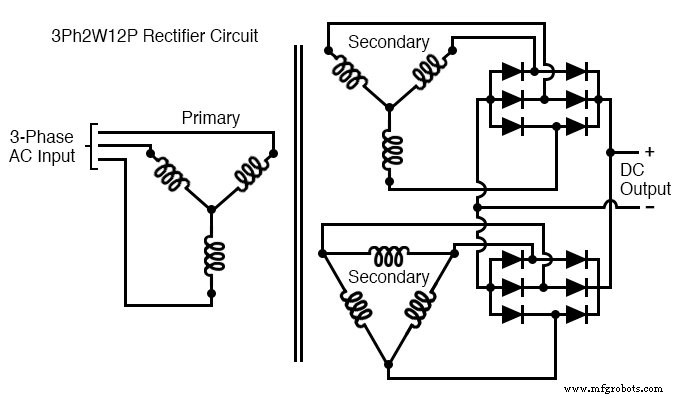
Beyond Six Pulses: 12‑Pulse Configurations
By employing transformers with 30° phase shifts (Y‑Δ or Δ‑Y connections), two 3‑phase bridge rectifiers can be paralleled to produce 12 pulses per cycle, further reducing ripple. This technique is common in large‑scale industrial power supplies.
Key Takeaways
- Rectification converts AC to DC using devices that allow unidirectional current flow.
- Half‑wave rectifiers are simple but produce highly pulsating DC.
- Full‑wave rectifiers—center‑tap or bridge—deliver smoother DC and are suitable for most power supplies.
- Polyphase rectification yields even smoother DC with lower ripple, advantageous for high‑power, low‑noise applications.
Related Worksheets
Industrial Technology
- Understanding AC Circuits: A Beginner's Guide
- Constructing a Reliable Low‑Voltage AC/DC Power Supply: Bridge Rectifier & Capacitive Filter
- Digital Integrated Circuits: Foundations and Best Practices
- Power Sources: AC and DC Explained
- Power Supply Circuits: Types, Design Principles, and Performance
- Crystal and Transistor Radio Circuits: From Basic Detectors to Integrated AM/FM Receivers
- Control Circuits: Fundamentals, Applications, and Best Practices
- Understanding Power in Electric Circuits: Measurement & Significance
- Understanding Power in Resistive and Reactive AC Circuits
- Bulldozer Technology: Design, Manufacturing, and Future Innovations