


Bridge Circuits: Wheatstone, Kelvin, and Their Role in Precise Electrical Measurements
Every comprehensive discussion of electrical metering must address bridge circuits. These sophisticated arrangements use a null‑balance meter to compare two voltages, much like a laboratory balance scale compares two weights and signals when they are equal. While a simple potentiometer circuit measures an unknown voltage, bridge circuits extend that principle to evaluate a wide range of electrical parameters, with resistance measurement being the most common application.
Wheatstone Bridge
The classic Wheatstone bridge looks like this:
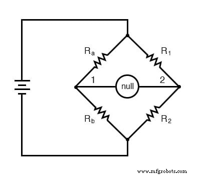
When the voltage between point 1 and the negative side of the battery equals the voltage between point 2 and the battery’s negative terminal, the null detector reads zero and the bridge is said to be “balanced.” This balance depends only on the ratios \(R_a/R_b\) and \(R_1/R_2\), and is essentially independent of the supply voltage.
To determine an unknown resistance, place the unknown \(R_x\) in the role of either \(R_a\) or \(R_b\). The remaining three resistors are precision standards whose values are known to high accuracy. Adjust one of the known resistors until the bridge balances, then calculate \(R_x\) from the ratio of the known resistances:
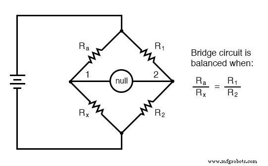
Each arm of the bridge is simply a resistor. The arm that includes the unknown \(R_x\) is often called the “rheostat,” while the other two arms are referred to as the “ratio” arms.
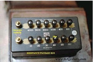
Accurate and stable resistance standards are relatively easy to build. Early scientific laboratories relied on mechanical resistance standards, such as the antique device pictured below, which adjusted resistance in discrete steps by inserting removable copper plugs into sockets.
Compared with a series battery‑movement‑resistor meter, the Wheatstone bridge offers a linear relationship between voltages and resistances, resulting in far greater precision. With high‑quality reference resistors and a sensitive null detector, accuracies better than ±0.05 % are routinely achieved, making the Wheatstone bridge the method of choice in calibration laboratories worldwide.
While the basic Wheatstone bridge measures resistance, its DC and AC variants can also determine inductance, capacitance, and even frequency in alternating‑current applications.
Kelvin Double Bridge
For measuring very low resistances—typically below 0.1 Ω—the Kelvin Double Bridge provides the necessary precision. Its schematic is shown below:
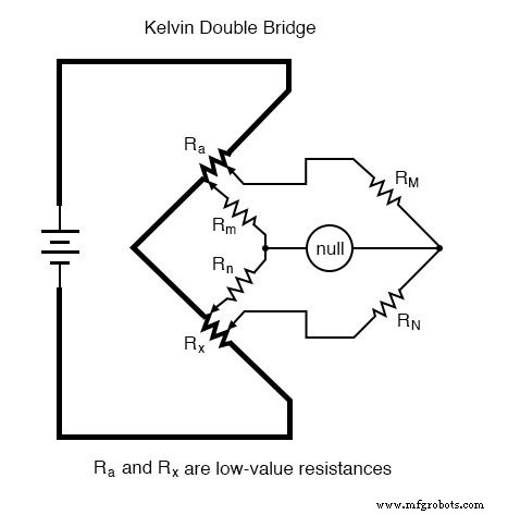
In a standard Wheatstone bridge, stray resistance in the connecting leads can dominate the measurement when the resistances under test are so small. The Kelvin configuration mitigates this by adding two additional resistors (\(R_m\) and \(R_n\)) and by placing the null detector between the two near ends of the unknown resistor and the low‑resistance standard. This arrangement eliminates voltage drops across the leads from affecting the balance.
When the bridge is balanced, the following relationship holds:
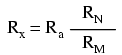
In practice, the ratios \(R_m/R_n\) and \(R_M/R_N\) are matched, so the balance equation reduces to the familiar Wheatstone form \(R_x/R_a = R_N/R_M\). This simplification eliminates the influence of lead resistance, provided the matching condition is met.
In many high‑precision setups, \(R_m\) and \(R_n\) are chosen to be as low as 1/100 of their counterpart ratio arms. This reduces series resistance in the null detector and enhances sensitivity, though it also increases the current through these small resistors and can amplify junction‑resistance effects. Designers therefore must strike a balance between sensitivity and error sources to achieve the desired accuracy.
Review
- Bridge circuits compare two voltages using a null detector, enabling highly accurate measurements.
- The Wheatstone bridge measures resistance by comparing an unknown resistor to precision standards, analogous to a laboratory scale.
- The Kelvin Double Bridge is tailored for low‑resistance measurements, adding complexity to suppress lead‑resistance errors.
Related Worksheets
- DC Bridge Circuit Worksheet
- AC Bridge Circuit Worksheet
Industrial Technology
- Exploring Nonlinear Resistance in Incandescent Lamps: A Practical Lab Guide
- Foundations of DC Circuits: Understanding Direct Current and Core Electrical Concepts
- Understanding AC Circuits: A Beginner's Guide
- Full-Wave Bridge Rectifier: Design, Benefits, and Practical Implementation
- Crystal and Transistor Radio Circuits: From Basic Detectors to Integrated AM/FM Receivers
- Control Circuits: Fundamentals, Applications, and Best Practices
- Resistors: Fundamentals, Types, and Practical Applications
- Understanding Conductance: The Inverse of Resistance
- Calculating Wire Resistance for Voltage‑Drop‑Critical Circuits
- AC Bridge Circuits: Precise Impedance Measurement with Balanced Ratios