


Understanding Conductance: The Inverse of Resistance
When students first encounter the parallel‑resistance equation, the natural question is, "Where did that come from?" It’s a surprising piece of arithmetic, and its origin deserves a clear explanation.
What Is the Difference Between Resistance and Conductance?
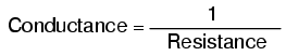
Resistance measures the friction a component offers to current flow. Symbolized by R and measured in ohms, it tells you how difficult it is for electrons to move through a device. Conductance, on the other hand, tells you how easy that flow is. Mathematically, conductance is simply the reciprocal of resistance:
The greater the resistance, the less the conductance—and vice versa. This inverse relationship means that resistance and conductance describe the same electrical property from opposite perspectives.
For example, if component A has half the resistance of component B, it is twice as conductive. If A’s resistance is one‑third that of B, A is three times more conductive.
The Unit of Conductance
To represent conductance, the symbol G and the unit mho (ohm spelled backward) were originally used. The mho was later renamed Siemens (S), honoring Werner von Siemens. Like Celsius and Hertz, the new name pays homage to a scientist while the unit’s value remains unchanged. Note that the unit is always written with a trailing “s” (Siemens), reflecting the proper spelling of the surname.
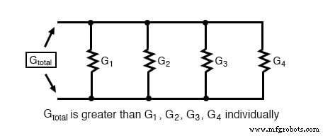
In a parallel circuit, multiple current paths lower the overall resistance, because current can flow more freely through several branches. Conversely, adding branches increases total conductance.
Total Parallel Resistance
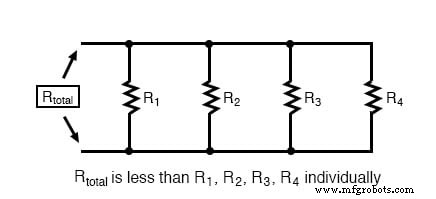
When resistors are connected in parallel, the combined resistance is always less than any individual branch resistance:
Total Parallel Conductance
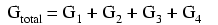
Parallel conductances simply add together:
Mathematically, the total conductance equals the sum of the individual conductances:
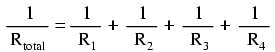
Replacing each conductance with its reciprocal resistance gives the familiar parallel‑resistance formula:
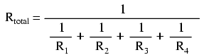
Finally, inverting both sides yields the classic expression for total resistance in parallel:
Because conductance is rarely measured directly, this derivation is a key insight when analyzing parallel circuits.
REVIEW:
- Conductance is the opposite of resistance: the measure of how easy it is for current to flow.
- It is symbolized by G and measured in mhos or Siemens.
- Mathematically, G = 1/R.
RELATED WORKSHEETS:
- Ohm’s Law Worksheet
- Specific Resistance of Conductors Worksheet
Industrial Technology
- Exploring Nonlinear Resistance in Incandescent Lamps: A Practical Lab Guide
- Understanding Electrical Resistance and Circuit Safety
- Resistors: Fundamentals, Types, and Practical Applications
- Bridge Circuits: Wheatstone, Kelvin, and Their Role in Precise Electrical Measurements
- Battery Construction Fundamentals: Cells, Internal Resistance, and Connectivity
- Calculating Wire Resistance for Voltage‑Drop‑Critical Circuits
- Temperature Coefficient of Resistance: How Temperature Alters Conductivity
- Understanding Conductance, Susceptance, and Admittance in AC Circuits
- Enhancing Product Durability: Mastering Polyurethane Impact Resistance
- Polyurethane: The Leading Choice for Superior Abrasion Resistance