


High‑Voltage Ohmmeter Design and Application
Conventional ohmmeters, as illustrated in the preceding chapter, typically employ low‑voltage sources—usually nine volts or less. Such a supply is adequate for measuring resistances up to a few mega‑ohms, but it falls short when the target resistance approaches the giga‑ohm range. A 9‑V battery cannot drive enough current to produce a readable deflection on an electromechanical meter under these extreme conditions.
Resistance in many materials, especially non‑metals, is not a constant linear parameter. At high electric fields, conduction mechanisms such as ionization or dielectric breakdown can cause the resistance to vary dramatically. A classic example is the current–voltage curve for a small air gap (less than an inch), where the conduction jumps from insulating to conducting as the voltage surpasses the air breakdown threshold.

Because a low‑voltage battery cannot reach the ionization potential of gases or the breakdown voltage of solid insulators, a high‑voltage ohmmeter is required for accurate measurement of such extreme resistances.
Simple High‑Voltage Ohmmeter
The most straightforward approach is to replace the low‑voltage battery with a higher‑voltage source while retaining the basic ohmmeter architecture.
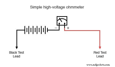
However, because the resistance of many materials changes with applied voltage, it is desirable to adjust the supply voltage to examine the device under different stress levels. This introduces a calibration challenge: a meter that deflects fully at a particular current will report a different resistance when the source voltage changes, unless the meter movement itself is designed to provide a stable deflection for a given resistance regardless of voltage.
Achieving this stability requires a specialized meter movement, unique to megohmmeters (commonly called meggers).
Megger Meter
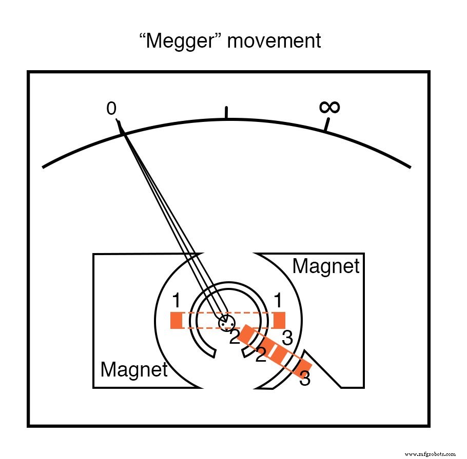
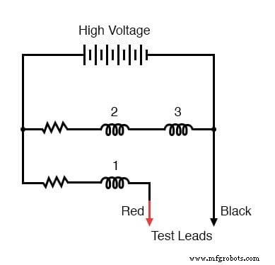
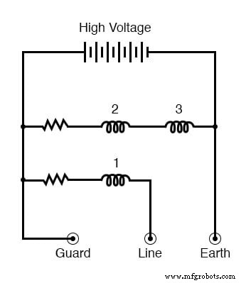
The numbered rectangular blocks represent three wire coils that are mechanically linked to the needle. Unlike a standard movement, there is no spring to return the needle; when unpowered the needle will float. The coils are wired as follows:
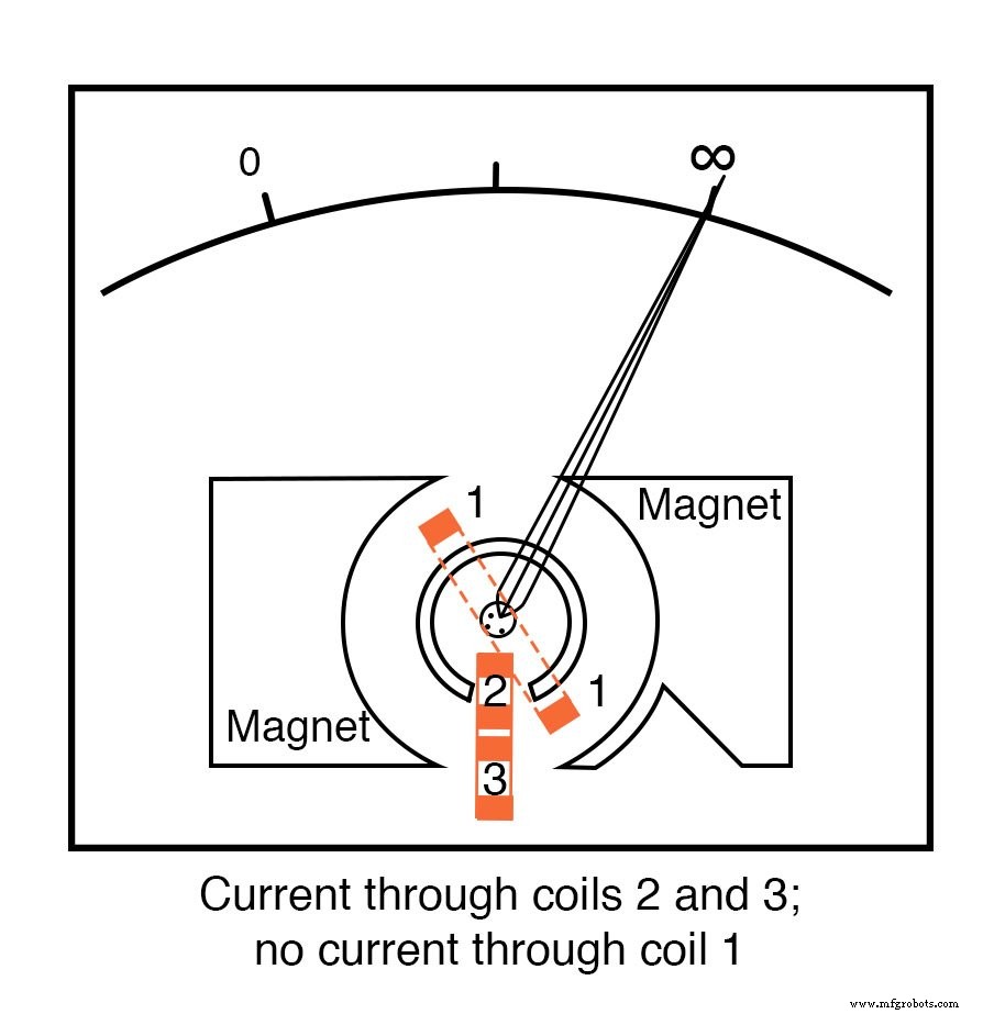
With the test leads open, only coils 2 and 3 are energized, drawing the needle fully to the right to indicate “infinity.” When a load is applied, current flows through coil 1, pulling the needle left toward zero. The internal resistor network is calibrated so that a shorted test lead forces the needle to the 0 Ω mark.
Because variations in battery voltage affect both the left‑ward (coil 1) and right‑ward (coils 2 + 3) torques proportionally, the net deflection remains consistent. Thus, the meter’s accuracy is independent of supply voltage; only the measured resistance itself may change with applied voltage, which is a desirable characteristic when assessing non‑linear materials.
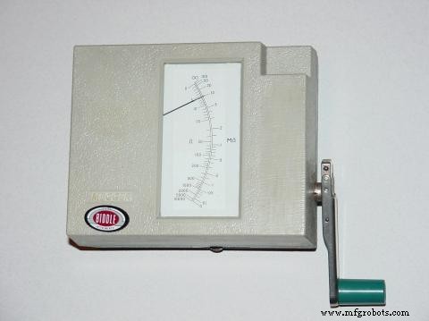
For safety, most meggers use a hand‑crank generator capable of up to 1 kV DC. The operator’s shock self‑terminates the cranking, and a slip clutch keeps the voltage stable across a range of cranking speeds. Many units offer selectable voltage outputs via a selector switch.
Battery‑powered meggers provide higher precision and are typically activated by a momentary‑contact pushbutton to eliminate lingering shock hazards.
Real Meggers
Field‑ready meggers feature three terminals: Line, Earth, and Guard. The measurement is taken between Line and Earth, while Guard is used to isolate one conductor from another during insulation tests.
For example, to test the insulation resistance of a two‑wire cable, connect the Line lead to one conductor and the Earth lead to a wire wrapped around the cable sheath. The Guard lead is then tied to the other conductor to keep the two conductors at nearly equal potential, preventing leakage current between them and ensuring that the meter reads only the resistance from the selected conductor to the sheath.
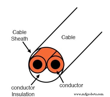
Without Guard, the measured value would be the parallel combination of the conductor‑to‑conductor resistance and the first conductor’s insulation resistance, potentially obscuring the true insulation quality of the second conductor.
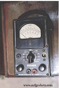
Meggers are portable field instruments, enabling technicians to detect high‑resistance “short” faults caused by wet or degraded insulation. Their high test voltages render them less susceptible to stray voltages (sub‑volt electrochemical potentials or induced fields) that can affect standard ohmmeters.
Hi‑Pot Testers
For more demanding insulation evaluations, a hi‑pot tester—capable of producing voltages above 1 kV—is employed. These devices test the integrity of oil, ceramic insulators, and other high‑voltage equipment. Due to the potentially destructive nature of excessive voltage, hi‑pot testers must be operated only by trained personnel following strict safety protocols.
Both hi‑pot testers and meggers can damage insulation if applied improperly. Once an insulating material undergoes breakdown, its ability to resist electrical conduction is permanently degraded. Proper training and adherence to manufacturer guidelines are essential to prevent accidental failure.
RELATED WORKSHEETS:
- Basic Ohmmeter Use Worksheet
Industrial Technology
- Practical Ohm’s Law Experiment: Measuring Voltage, Current, and Resistance
- Ohm’s Law Explained: How Voltage, Current, and Resistance Interact in Electrical Circuits
- Resistors: Fundamentals, Types, and Practical Applications
- Nonlinear Conduction: How Resistance Changes Shape Real-World Circuits
- Understanding Conductance: The Inverse of Resistance
- High‑Voltage PCB Design: Materials, Safety, and Best Practices
- High-Current Voltage Regulator: The Complete Expert Guide
- High-Frequency Grade Electrical Steel – 0.20 mm Thin Gauge (EN 10303:2015 Compliant)
- Printdur® HSA: High-Strength, Nickel-Free Steel for LPBF
- PAEK Filaments: High-Performance Materials for 3D Printing