


Multimeters: From Analog to Digital – A Comprehensive Guide
Because a single meter movement can be configured as a voltmeter, ammeter, or ohmmeter by simply connecting it to different external resistor networks, it follows that a single device – the multimeter – can perform all three functions in one compact unit when equipped with the appropriate switches and resistors.
For most electronics work, the multimeter is the quintessential tool. It offers a broad range of measurements – voltage, current, resistance, and more – in a single, affordable package that is both simple to operate and highly reliable. With the advent of solid‑state technology, modern multimeters have evolved from basic analog devices to sophisticated digital instruments, yet the core principle remains unchanged.
Analog Multimeter
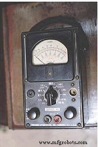
The handheld analog multimeter shown above features separate ranges for voltage, current, and resistance. Each function has its own scale on the meter movement, and the rotary selector switch allows the user to choose the appropriate range. The test leads are inserted into the two copper jacks at the bottom of the meter face, marked –TEST+ (black) and +TEST (red).
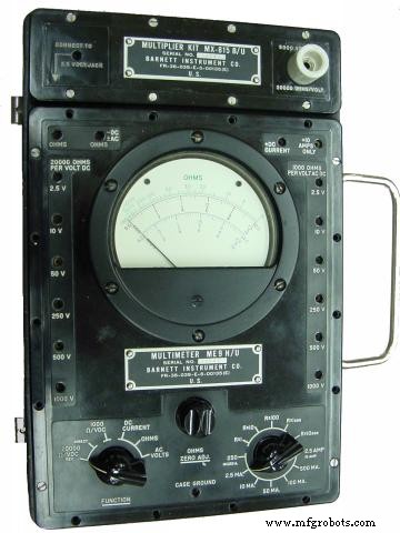
The Barnett model takes a slightly different approach. Its rotary switch has fewer positions, but it offers many more jacks for the test leads. Each jack is labeled with a full‑scale range, making it easy to identify the correct connection for the desired measurement.
Digital Multimeter
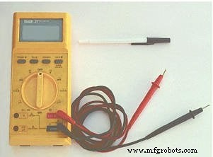
In contrast to analog meters, digital multimeters replace the needle with a gray LCD display that shows numerical readings. The example shown has a rotary selector switch and four jacks for the test leads. The black lead is common to all functions, while the red lead can be inserted into one of three jacks labeled for voltage, resistance, or current (A, mA, µA).
Requiring the user to move the red lead between jacks to switch from voltage to current measurement is a safety feature that helps prevent accidental short‑circuiting when the meter is set to measure current with a low input impedance.
Unlike analog meters, this digital unit is auto‑ranging: it automatically selects the appropriate range for the measured quantity, eliminating the need for the user to change settings manually. However, not all digital meters support autoranging, so always consult the manual for your specific model.
Because no two multimeter models are identical—even within the same brand—consulting the owner’s manual is essential for understanding the exact operation of your instrument.
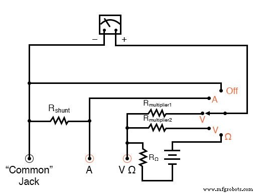
Below is a schematic for a simple analog volt/ammeter configuration:
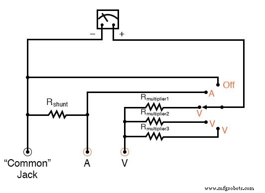
In the switch’s three counter‑clockwise positions, the meter movement is connected to the Common and V jacks through one of three series resistors (Rmultiplier1–Rmultiplier3), functioning as a voltmeter. The fourth position connects the meter in parallel with the shunt resistor, creating an ammeter. The final clockwise position short‑circuits the movement through the switch, providing a damping effect that protects the needle from mechanical shock.
To add an ohmmeter function, one of the voltage ranges can be replaced as illustrated below:
With voltage, resistance, and current capabilities, this device is also known as a volt‑ohm‑milliammeter (VOM).
Reading an analog multimeter with multiple ranges may seem intimidating, but the meter movement contains several scales that correspond to each range. A close‑up of the Barnett meter’s scales is shown here:
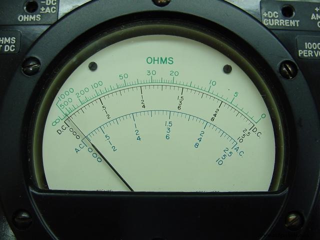
Three types of scales are present: green for resistance at the top, black for DC voltage and current in the middle, and blue for AC voltage and current at the bottom. Each DC/AC section has sub‑scales of 0–2.5, 0–5, and 0–10, and the operator must match the selected range and plug position with the appropriate scale to interpret the needle correctly.
Typical voltage ranges on this meter include 2.5 V, 10 V, 50 V, 250 V, 500 V, and 1 kV. With a voltage‑range extender, measurements up to 5 kV are possible. For instance, selecting the 10‑V jack requires reading the 10‑scale, whereas selecting the 250‑V jack means reading the 2.5‑scale and multiplying by 100.
When measuring current, the red lead is inserted into a dedicated jack and the rotary switch selects the range. The following image shows the switch set to 2.5 mA:
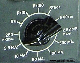
Current ranges are always multiples of the three meter scales: 2.5, 5, and 10. For the 2.5 mA setting, the needle is read directly on the 0–2.5 scale. For other ranges such as 250 µA, 50 mA, 100 mA, or 500 mA, the reading on the appropriate scale must be multiplied by 10 or 100 to obtain the actual value.
The highest current range is achieved with the switch in the 2.5/10 A position. The difference between 2.5 A and 10 A is made by inserting the red lead into a special 10 A jack adjacent to the regular current jack.
Resistance is displayed on a non‑linear, “backward” scale that runs from zero (right side) to infinity (left side). Only one jack is provided for ohm measurements, so the range is set solely by the rotary switch. Five multiplier settings are available: Rx1, Rx10, Rx100, Rx1000, and Rx10000. The displayed needle value is multiplied by the selected factor to give the true resistance.
RELATED WORKSHEETS:
- Ammeter - Multimeter Worksheet
- Voltmeter - Multimeter Worksheet
Industrial Technology
- Mastering Ohmmeter Measurements: A Practical Guide to Resistance Testing
- Circuit With a Switch: A Practical Guide to Basic Electrical Circuits
- Commutating Diode Experiment: Suppressing Inductive Kickback with a Neon Lamp
- Using a Transistor as an Electrically Controlled Switch
- Understanding Electrical Switches: Types, Functions, and Applications
- Eliminating Contact Bounce in Mechanical Switches
- Understanding Meter Design: From Classic Galvanometers to Modern Digital Displays
- Mastering the C# Switch Statement: Syntax, Examples & Best Practices
- DIY Frequency Meter – Measure Up to 6.5 MHz with Arduino Nano
- Professional Wiring Guide for Combo Switch/Outlet Devices – Diagrams & Installation Tips