


Understanding Meter Design: From Classic Galvanometers to Modern Digital Displays
A meter is a precision instrument that measures an electrical quantity—voltage, current, or resistance—and presents the value in a format easily readable by a human. Typically, this involves a visual indicator such as a moving pointer on a calibrated scale, a bar graph of illuminated LEDs, or a digital numeric display. This article focuses on the fundamentals of meter movement design and the principles behind the most common types of meters.
What Is a Meter Movement?
The term movement refers to the core mechanism that converts an electrical measurement into a visible indication. Although modern meters are predominantly digital, the word "movement" remains in use to describe the underlying display function.
Electromagnetic Meter Movements
Electromagnetic (or moving‑coil) movements rely on the magnetic field generated by current flowing through a coil. When this field interacts with a stationary magnetic field, a torque is produced that moves a needle or pointer. The magnitude of the torque—and therefore the pointer displacement—is directly proportional to the current magnitude.
Early examples, such as the simple string galvanometer, used a magnetized needle suspended by a thread inside a coil. Modern precision instruments employ a permanent‑magnet, moving‑coil (PMMC) design that offers high sensitivity, minimal drift, and robust operation in noisy environments.
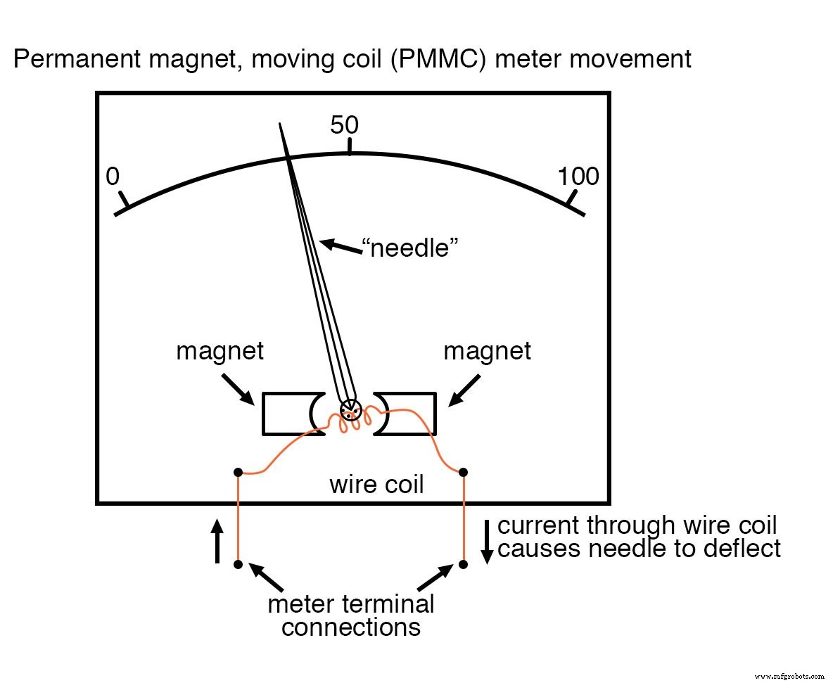
In a typical PMMC meter, the needle sweeps from a zero mark on the left to a full‑scale mark on the right. A 50 µA full‑scale movement, for example, would have 0 µA at the left end, 50 µA at the right, with intermediate graduations (often 5 µA or 1 µA) for fine resolution. The movement’s polarity sensitivity means that current direction determines needle direction, which is ideal for DC measurements but unsuitable for AC unless the meter is specifically designed to handle it.
Some movements feature a centrally spring‑balanced needle, allowing them to display both positive and negative values. Polarity‑insensitive designs, such as iron‑vane meters, deflect a movable iron vane toward a stationary wire and are ideal for AC measurements.
Electrostatic Meter Movements
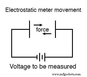
Electrostatic movements use the attractive or repulsive force between charged plates to deflect a pointer. The force is proportional to the voltage applied and inversely proportional to the square of the plate separation, and it is independent of polarity. Although the resulting forces are very small—making these designs unsuitable for routine measurements—they excel at measuring extremely high voltages due to their high internal resistance, which draws negligible current from the circuit under test.
Cathode Ray Tube (CRT) Meter Movements
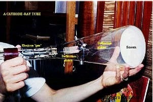
CRT meters employ an electron beam deflected by electrostatic plates. The beam’s position, illuminated by phosphor coating, indicates the voltage level. While accurate for high‑voltage measurement and capable of displaying dynamic waveforms when integrated into an oscilloscope, CRTs are bulky, power‑hungry, and fragile compared to modern solid‑state devices.
Full‑Scale Indication and Range Extension
Each meter movement has a specified full‑scale deflection value—either a current for electromagnetic movements or a voltage for electrostatic ones. To measure larger ranges, the movement is combined with a voltage or current divider circuit. Precision resistors scale the input signal to the movement’s optimal range, enabling the meter to display values from microamps to thousands of volts.
Key Takeaways
- A movement is the display mechanism of a meter.
- Electromagnetic movements use magnetic fields generated by current; common examples include D’Arsonval, Weston, and iron‑vane designs.
- Electrostatic movements rely on forces between charged plates and are suitable for very high‑voltage measurement.
- Cathode Ray Tubes (CRTs) bend an electron beam with electrostatic fields to provide a visual indication of voltage.
Further Learning
- Ammeter Design Worksheet
- Voltmeter Design Worksheet
Industrial Technology
- Understanding Alternating Current (AC): Why It Powers the World
- Panel Meters Explained: How They Monitor and Control Industrial Equipment
- What Is a Current Meter? A Guide to Measuring Electrical Current
- Understanding Current Regulators: How They Protect Your Devices
- Understanding Phase Meters: Accurate Measurement of Electrical Power
- Understanding Wattmeters: Types, Functions, and How They Measure Electrical Power
- Understanding Pulsed DC: A Hybrid Current for Modern Electronics
- Understanding Breaking Capacity: Key Facts for Safe Electrical Protection
- Understanding Bias Voltage: Definition and Impact on Electronic Devices
- Understanding Overcurrent Relays: Protecting Circuits from Overload