


Designing Precision Voltmeter Ranges: From Sensitive Movements to Full‑Scale Readings
Most meter movements are highly sensitive. For instance, some D’Arsonval movements are rated for a full‑scale deflection current as low as 50 µA, with an internal wire resistance below 1 kΩ. This limits the movement’s direct full‑scale voltage to only 50 mV (50 µA × 1 kΩ). To build practical voltmeters capable of measuring higher voltages, we must attenuate the input voltage so that only a safe fraction reaches the movement.
D’Arsonval Movement Example
Consider a D’Arsonval movement with a full‑scale deflection rating of 1 mA and a coil resistance of 500 Ω. Using Ohm’s law, the voltage that drives this movement to full scale is:
E = I R
E = (1 mA)(500 Ω) = 0.5 V
Thus, the bare movement can read up to 0.5 V. To extend its range beyond this value, we need a proportioning circuit that limits the voltage across the movement while allowing the meter to display higher applied voltages.
When we add a series resistor – the so‑called multiplier resistor – the movement becomes part of a voltage divider. The total voltage applied to the series pair is split between the multiplier and the movement, ensuring only the appropriate fraction reaches the coil.
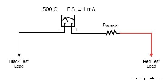
Calculating the Multiplier Resistor
Suppose we want the 1 mA, 500 Ω movement to reach full scale at an applied voltage of 10 V. We first set up an E/I/R table for the two series elements:
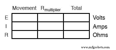
With the movement at full scale (1 mA) and the total applied voltage at 10 V, the table becomes:
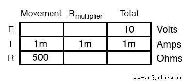
There are two common ways to find the multiplier resistance:
- Total resistance method: R_total = E/I = 10 V/1 mA = 10 kΩ. Subtract the movement’s 500 Ω to get R_multiplier = 9.5 kΩ.
- Voltage‑drop method: The movement drops 0.5 V (E = IR). The remaining 9.5 V must drop across the multiplier. Using R = E/I gives R_multiplier = 9.5 kΩ again.
Either approach confirms that a 9.5 kΩ multiplier is required. When 10 V is applied across the leads, 1 mA flows through the circuit, the movement sees exactly 0.5 V, and the needle points to full scale. The meter face is simply relabeled to read 0–10 V, so the user sees a correct 10‑volt reading without knowing the underlying division.

Thus, a sensitive movement is “fooled” by a precision resistor network into displaying a larger voltage. Ammeters use a parallel shunt resistor to divide current, but the underlying principle is identical.
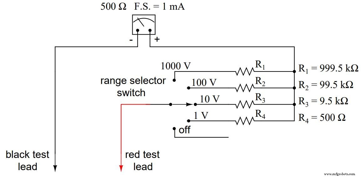
Multi‑Range Voltmeter Design
To provide a single movement with multiple voltage ranges, a multi‑pole selector switch contacts different multiplier resistors. A typical four‑range voltmeter (1 V, 10 V, 100 V, 1 kV) built on a 1 mA, 500 Ω movement would use the following resistor values:
These values are often impractical to source directly. Designers therefore use a stepped approach, selecting standard resistor values that add to the required total. For the 1 kV range, the selector contacts a 900 kΩ, 90 kΩ, 9 kΩ, and 500 Ω series stack:
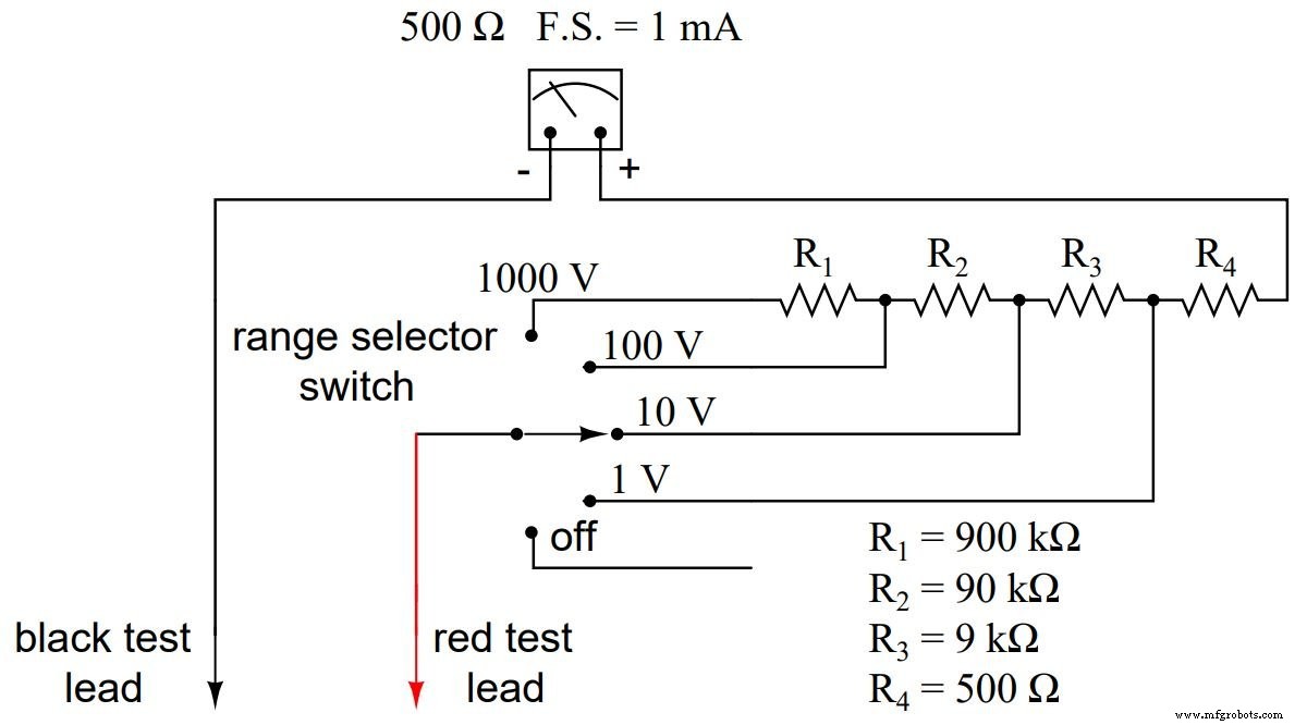
Adding these gives the exact 999.5 kΩ needed:
R_total = R4 + R3 + R2 + R1 = 900 kΩ + 90 kΩ + 9 kΩ + 500 Ω = 999.5 kΩ
From the user’s perspective, the meter behaves identically across all ranges; only the scale labels change.
Review
- Extended voltmeter ranges are achieved by adding series multiplier resistors that form a voltage divider.
- Each range uses a distinct resistor value or a combination of standard values.
- The movement’s sensitivity is preserved while enabling measurement of high voltages.
Related Worksheets
- Voltmeter Design Worksheet
- Voltmeter Worksheet
Industrial Technology
- Mastering Voltmeter Use: Accurate Voltage Measurement Made Simple
- Build a Custom Analog Multimeter: From Parts to Calibration
- Potentiometric Voltmeter: Precise Voltage Measurement with Minimal Loading
- Build a High‑Impedance Voltmeter with TL082 / LM1458 Op‑Amps
- Understanding Meter Design: From Classic Galvanometers to Modern Digital Displays
- Designing Precision Voltmeter Ranges: From Sensitive Movements to Full‑Scale Readings
- Ammeter Design: Shunt Resistor Techniques for Accurate Current Measurement
- Multimeters: From Analog to Digital – A Comprehensive Guide
- AC Voltage and Current Meter Design: From Rectification to True‑RMS Measurement
- Panel Meters: A Cost‑Effective Solution for Machine Interface and Control