


AC Voltage and Current Meter Design: From Rectification to True‑RMS Measurement
Electromechanical meter movements for alternating current are generally divided into two groups: adaptations of direct‑current (DC) designs and units specifically engineered for AC measurement.
Permanent‑magnet moving‑coil (PMMC) movements cannot be connected directly to AC. The needle would oscillate with each half‑cycle, producing a useless flutter (see figure below).
Permanent‑magnet devices, like motors, rely on the polarity of the applied voltage or current direction. When AC is applied, the polarity reverses every half‑cycle, causing the needle to move back and forth.
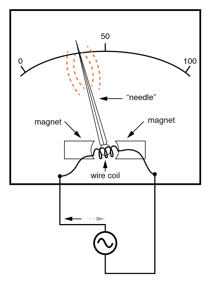
Passing AC through a D’Arsonval meter movement produces a rapid, ineffective needle flutter.
To employ a DC‑style movement such as the D’Arsonval design, the AC signal must first be rectified to DC. The most common method uses diodes, which act as one‑way valves for current flow. Four diodes arranged in a bridge configuration ensure that the current through the meter movement always flows in a single direction, regardless of the AC cycle.
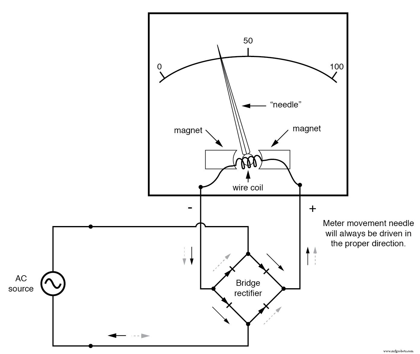
Rectified AC applied to a bridge‑rectified meter movement drives the needle consistently in one direction.
Alternatively, AC‑specific meter movements can be designed to avoid the polarity sensitivity inherent in DC types. A common approach uses a non‑magnetized iron vane that is attracted toward a stationary coil energized by the AC quantity being measured, as illustrated below.
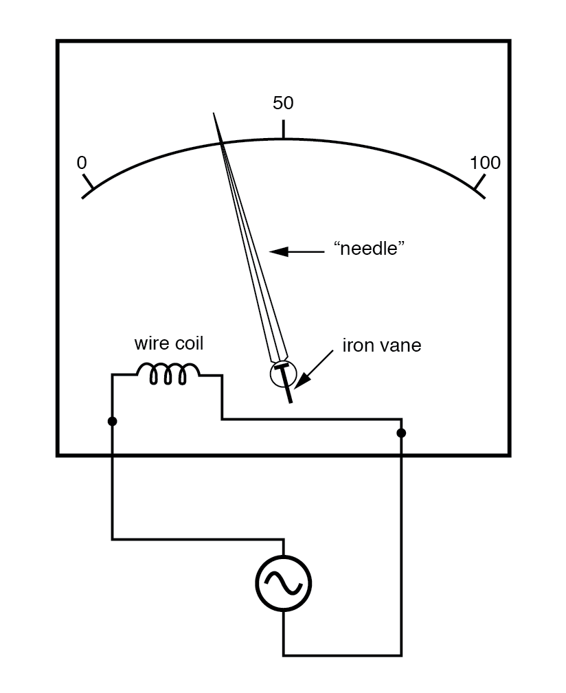
Iron‑vane electromechanical meter movement.
Electrostatic attraction between two metal plates separated by an air gap offers another mechanism for generating a needle‑moving force proportional to the applied voltage. While this method works equally well for AC and DC, the forces are typically very small, making such movements fragile and susceptible to disturbance. Nevertheless, electrostatic meters are attractive for high‑voltage AC applications because of their extremely high input impedance and the ability to measure large voltages without external range resistors.
When an electrostatic or other basic meter movement needs to be calibrated for AC use, series‑connected “multiplier” resistors or resistive voltage dividers are employed, just as in DC meter design:
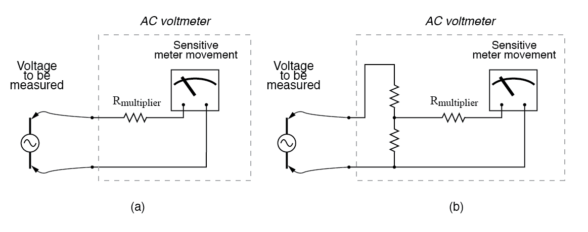
Multiplier resistor (a) or resistive divider (b) scales the range of the basic meter movement.
Using capacitors instead of resistors for the divider offers a non‑dissipative solution, eliminating heat generation. This technique is particularly advantageous for high‑voltage AC measurements.
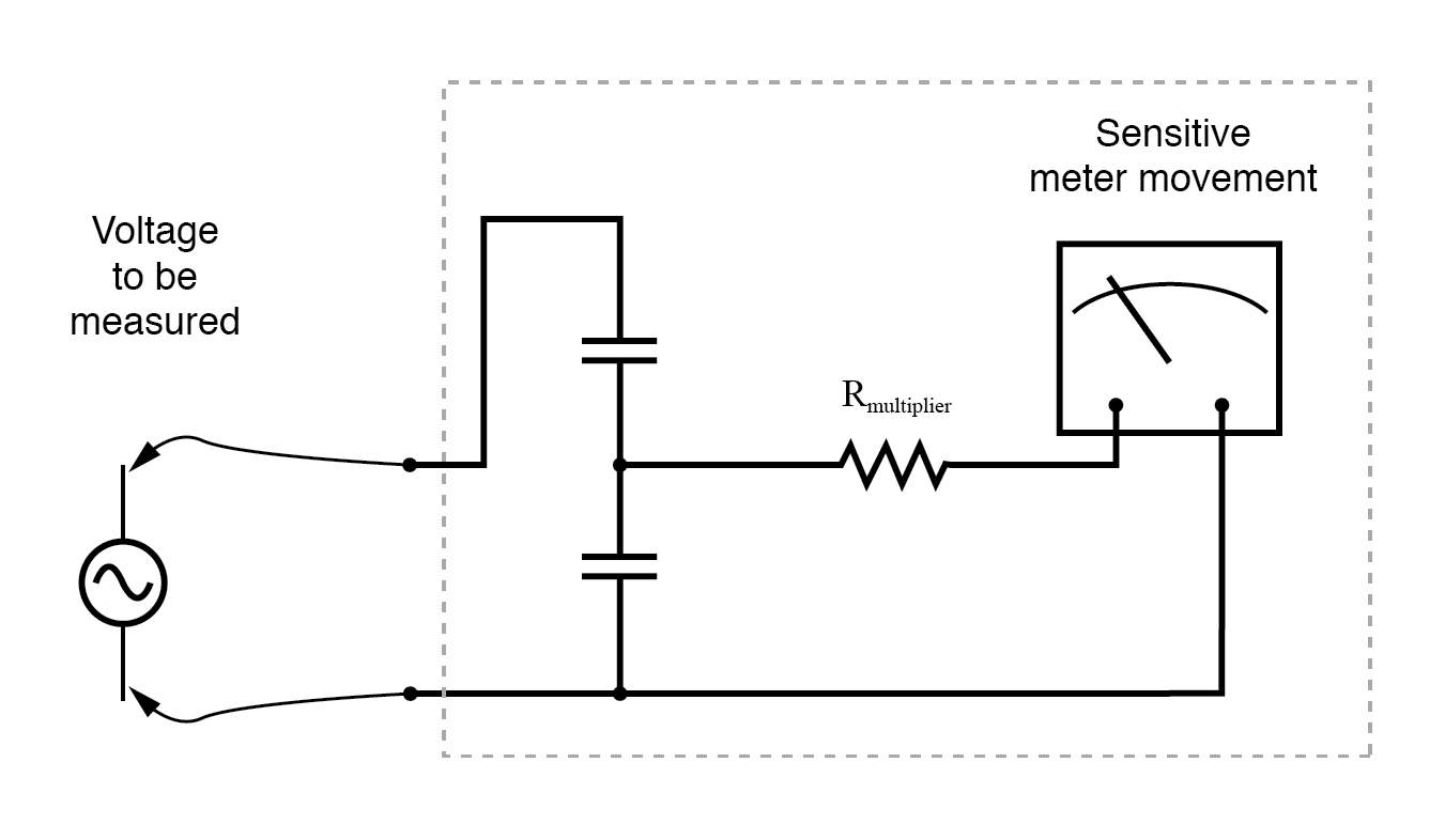
AC voltmeter employing a capacitive divider.
For electrostatic meter movements—which are inherently capacitive—a single “multiplier” capacitor can be added in series to extend the measurable voltage range, analogous to a resistor multiplier for moving‑coil meters.
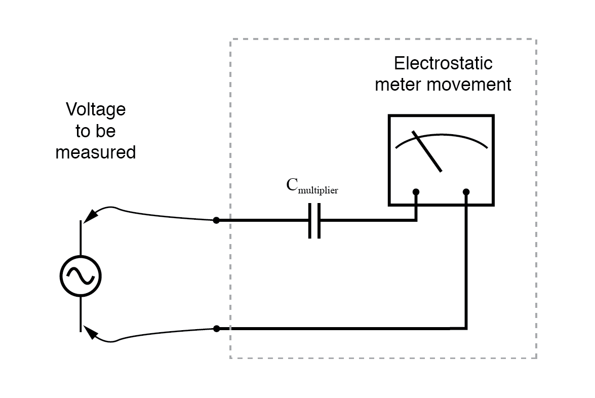
An electrostatic meter movement may use a capacitive multiplier to increase its range.
The cathode‑ray tube (CRT) metering approach, described in the DC chapter, is also well suited for AC voltage measurement. By sweeping the electron beam side‑to‑side across the screen while the AC signal drives vertical deflection, the device can display the waveform shape, not just a magnitude reading. However, CRTs are bulky, consume significant power, and are fragile due to their evacuated glass construction, limiting their practical use.
Electromechanical AC meter movements still play an essential role in many applications. A critical consideration for designers and users alike is the measurement of RMS (root‑mean‑square) values, which provide a meaningful comparison between AC and DC power.
While rectified D’Arsonval, iron‑vane, and electrostatic movements naturally deliver an average value of the instantaneous signal, this average is not equivalent to RMS. The following table illustrates the relationship between RMS, average, and peak‑to‑peak values for sine, square, and triangular waves:
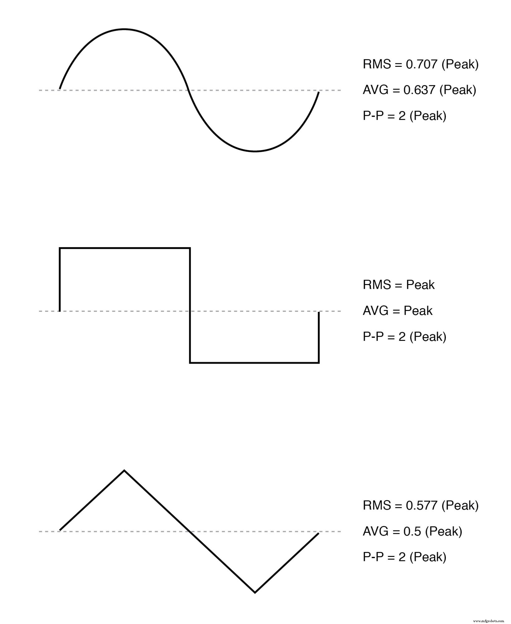
RMS, average, and peak‑to‑peak values for sine, square, and triangle waves.
Because electromechanical meters inherently report average values, designers often “cheat” by assuming the waveform is a pure sine. For a sine wave, RMS equals 0.707 times the peak value, whereas the average equals 0.637 times the peak. Dividing these gives an average‑to‑RMS conversion factor of 1.109:
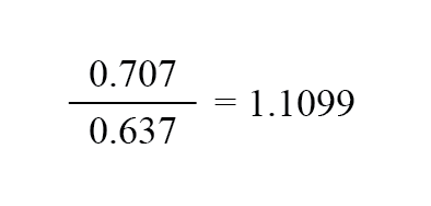
Accordingly, the meter movement is calibrated to indicate roughly 1.11 times the natural reading, which aligns with the true RMS value for sine waves. This approach fails for non‑sine waveforms such as triangle or square waves, where the RMS‑to‑average ratios differ significantly.
For square waves, RMS equals the average, but for triangular waves the conversion factor differs. These discrepancies become critical in modern power systems where harmonic distortion is common.
CRT meters, which display the peak or peak‑to‑peak of the waveform, also face this limitation; determining RMS from a peak measurement requires knowledge of the waveform shape.
A more robust solution is to design a meter that measures RMS directly by exploiting the definition of RMS as the heating value of an AC signal in a resistive load. By connecting the AC source across a resistor of known value and measuring the resulting heat with a thermocouple, the meter can provide a true‑RMS reading independent of waveform shape:
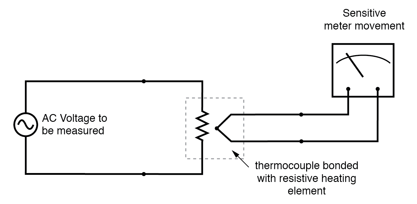
Direct‑reading thermal RMS voltmeter accommodates any wave shape.
Although the concept is straightforward, practical implementation presents engineering challenges. Nevertheless, the principle—converting electrical power into heat and measuring that heat—has been adopted in high‑end handheld multimeters for true‑RMS capability.
Calibrating AC voltmeters and ammeters across different ranges follows the same principles used for DC instruments: series multiplier resistors (or capacitors) extend voltage ranges, while parallel shunt resistors accommodate higher currents. In addition, transformers—particularly potential transformers (PTs) and current transformers (CTs)—enable electromagnetic stepping of ranges, allowing small meter movements to measure large voltages or currents with electrical isolation.
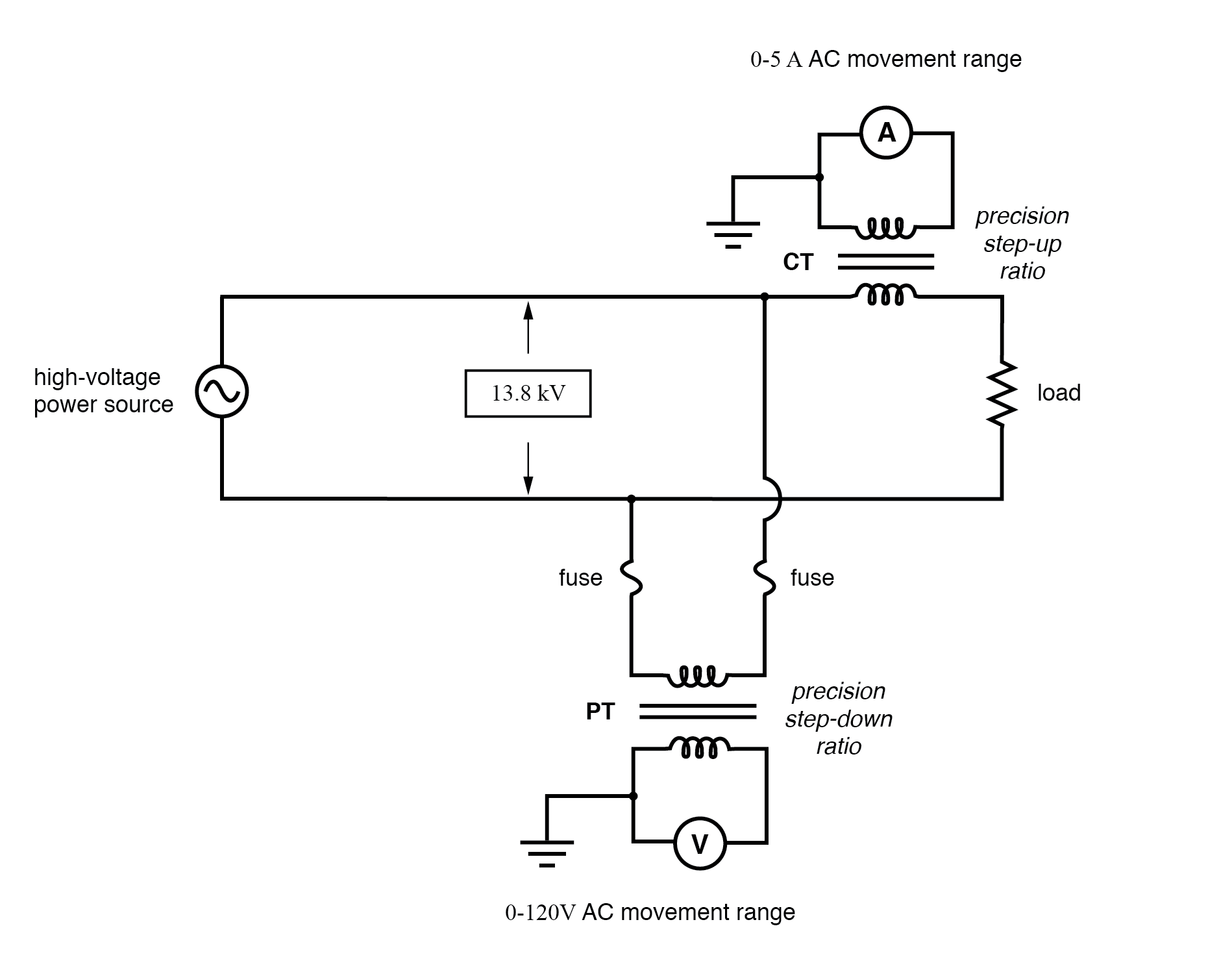
CT scales current down; PT scales voltage down.
In a typical three‑phase AC panel, toroidal CTs are placed behind the meter housing, while three 5‑A full‑scale AC ammeters indicate the current in each conductor through the CTs. When the panel is decommissioned, the CTs remain, but the conductors are no longer present:
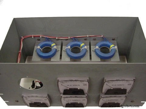
Toroidal CTs scale high current levels down for 5‑A AC ammeters.
Because instrument transformers are expensive and often large, they are reserved for high‑voltage or high‑current applications. For lower‑range measurements—such as scaling a milliamperage meter to 120 V or 5 A—precision resistors (multipliers and shunts) are used, just as with DC meters.
REVIEW:
- Polarized (DC) meter movements require diodes to measure AC quantities.
- Electromechanical meter movements—whether electromagnetic or electrostatic—naturally provide average values; they can be calibrated to indicate RMS only if the waveform shape is known in advance.
- True‑RMS meters employ specialized technology to deliver accurate RMS indications regardless of waveform.
Industrial Technology
- Build a Custom Analog Multimeter: From Parts to Calibration
- Build a High‑Impedance Voltmeter with TL082 / LM1458 Op‑Amps
- Decoding Numbers and Symbols in Electronics
- Understanding Meter Design: From Classic Galvanometers to Modern Digital Displays
- Designing Precision Voltmeter Ranges: From Sensitive Movements to Full‑Scale Readings
- Multimeters: From Analog to Digital – A Comprehensive Guide
- Analyzing a Parallel R‑L‑C Circuit: Impedance, Current, and SPICE Simulation
- Measuring Frequency and Phase in AC Power Systems
- Case Study: Seamless Coil Width Adjustment via Linear Ball Bushing Upgrade
- Measuring AC and DC Current with Digital and Analog Multimeters: A Practical Guide