


Practical Guide to Power Factor Correction in AC Systems
When an AC system exhibits a low power factor, you typically cannot rely on precise inductance values for corrective calculations.
If available, a power‑factor meter provides the instantaneous power‑factor value (between 0 and 1) and the apparent power, which is obtained by multiplying the measured voltage by the measured current.
When a meter is unavailable, an oscilloscope can be employed to compare voltage and current waveforms, determine the phase shift in degrees, and compute the power factor as the cosine of that shift.
Typically, a wattmeter measures true (real) power. Comparing its reading with the apparent power calculated from voltage and current measurements yields both reactive power and the power‑factor value.
Example Problem
Below is a simplified representation of the measurement setup:
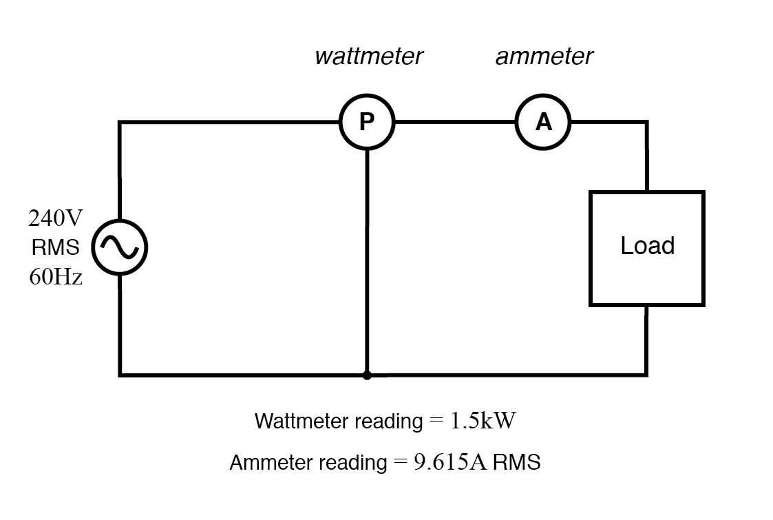
Wattmeter reads true power; the product of voltmeter and ammeter readings yields apparent power.
Calculating Apparent Power in kVA
The apparent power (S) is calculated by multiplying load voltage (V) by load current (I). Converting to kilovolt‑amps (kVA) simply divides by 1 000.
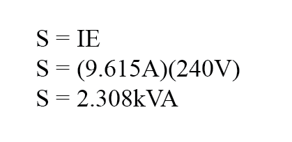
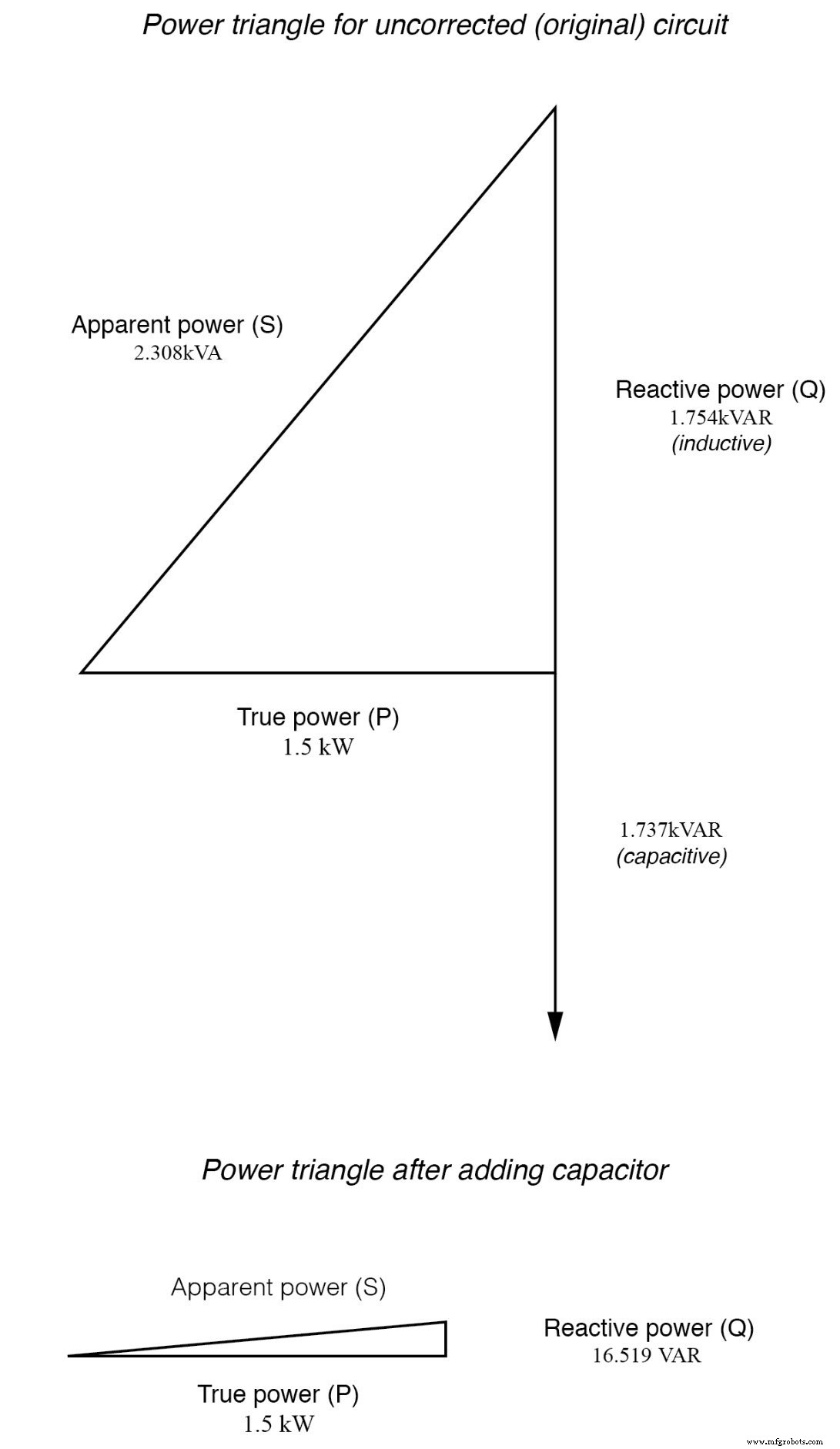
The result, 2.308 kVA, far exceeds the true power of 1.5 kW, indicating a power factor well below unity.
Determining Power Factor
Power factor (PF) is the ratio of true power (P) to apparent power (S):
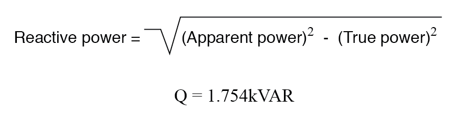
Reactive Power via the Pythagorean Theorem
With the apparent power as the hypotenuse and true power as the adjacent side, the reactive power (Q) is found by the Pythagorean theorem “backwards”:
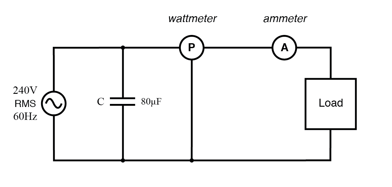
Correcting Power Factor with a Capacitor
Inductive loads—such as motors—present a lagging power factor. A capacitor bank wired in parallel provides leading reactive power to counteract the inductive contribution.
From the reactive power of 1.754 kVAR, the required capacitance (C) at 240 V is calculated as:
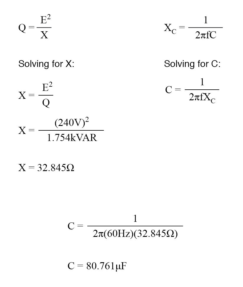
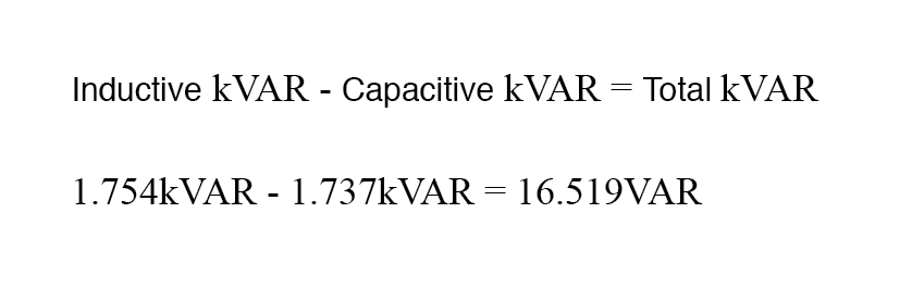
Rounded to 80 µF, the capacitor’s reactance (Xc) is 33.157 Ω, resulting in a current of 7.238 A and a reactive power of 1.737 kVAR (capacitor only). Because the capacitor current is 180° out of phase with the inductive current, its reactive power subtracts directly from the load’s reactive power.
Although true power remains unchanged, the apparent power and the total current drawn from the 240 V source are significantly reduced.
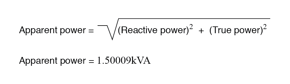
New apparent power is computed from the adjusted reactive power using the Pythagorean theorem:
Power triangle before and after capacitor correction.
Takeaway
Implementing a properly sized capacitor bank not only improves power factor but also lowers apparent power, reduces line currents, and can lead to substantial energy cost savings.
RELATED WORKSHEET:
- AC Power Worksheet
Industrial Technology
- Power Sources: AC and DC Explained
- Practical Considerations in Transformer Design: Power, Losses, and Performance
- Understanding Power in Resistive and Reactive AC Circuits
- Calculating Power Factor in AC Circuits: Theory, Impact, and Practical Correction
- Low Power Factor Explained: Key Causes & How to Fix Them
- Power Factor Improvement: Methods, Benefits, and Trade‑Offs
- Accurate Power Factor Correction: Capacitor Bank Calculator (kVAR & µF)
- Power Factor Correction Calculator: Find Capacitor Size in µF and kVAR Quickly
- Why Power Factor Matters: Key to Efficient Electrical Systems
- 10 Essential Tips for Designing Low‑Noise Amplifiers