


Calculating Power Factor in AC Circuits: Theory, Impact, and Practical Correction
The phase angle shown in the classic power‑triangle diagram is the key to understanding how efficiently an AC circuit uses electrical energy. It represents the ratio between the real (or true) power that does useful work and the apparent power drawn from the supply.
In polar form, the same angle describes the circuit’s impedance. When the real power is expressed as a fraction of the apparent power, we obtain the power factor (PF) – a dimensionless metric that ranges from 0 to 1.
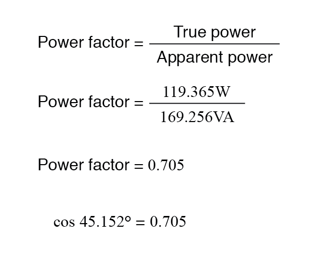
Because the real power (adjacent side) and apparent power (hypotenuse) form a right triangle, the power factor is simply the cosine of the phase angle:
Note that PF is unitless; it is a pure number.
Typical Power Factor Values
- Purely resistive load: PF = 1. The power triangle collapses to a horizontal line; reactive power is zero.
- Purely inductive load: PF = 0. The triangle becomes vertical; real power is zero and all power is reactive.
- Purely capacitive load: PF = 0 as well, with a vertical triangle pointing downward.
Why Power Factor Matters
When PF < 1, the supply must carry more current than would be needed for the same real power if the load were purely resistive. For example, a circuit that delivers 169.256 W with 1.410 A is operating at a PF of 0.705, whereas a purely resistive load would provide the same power with the same current but no reactive component.
Low PF leads to higher line losses, increased transformer and conductor size, and potential penalties from utilities.
Correcting a Poor Power Factor
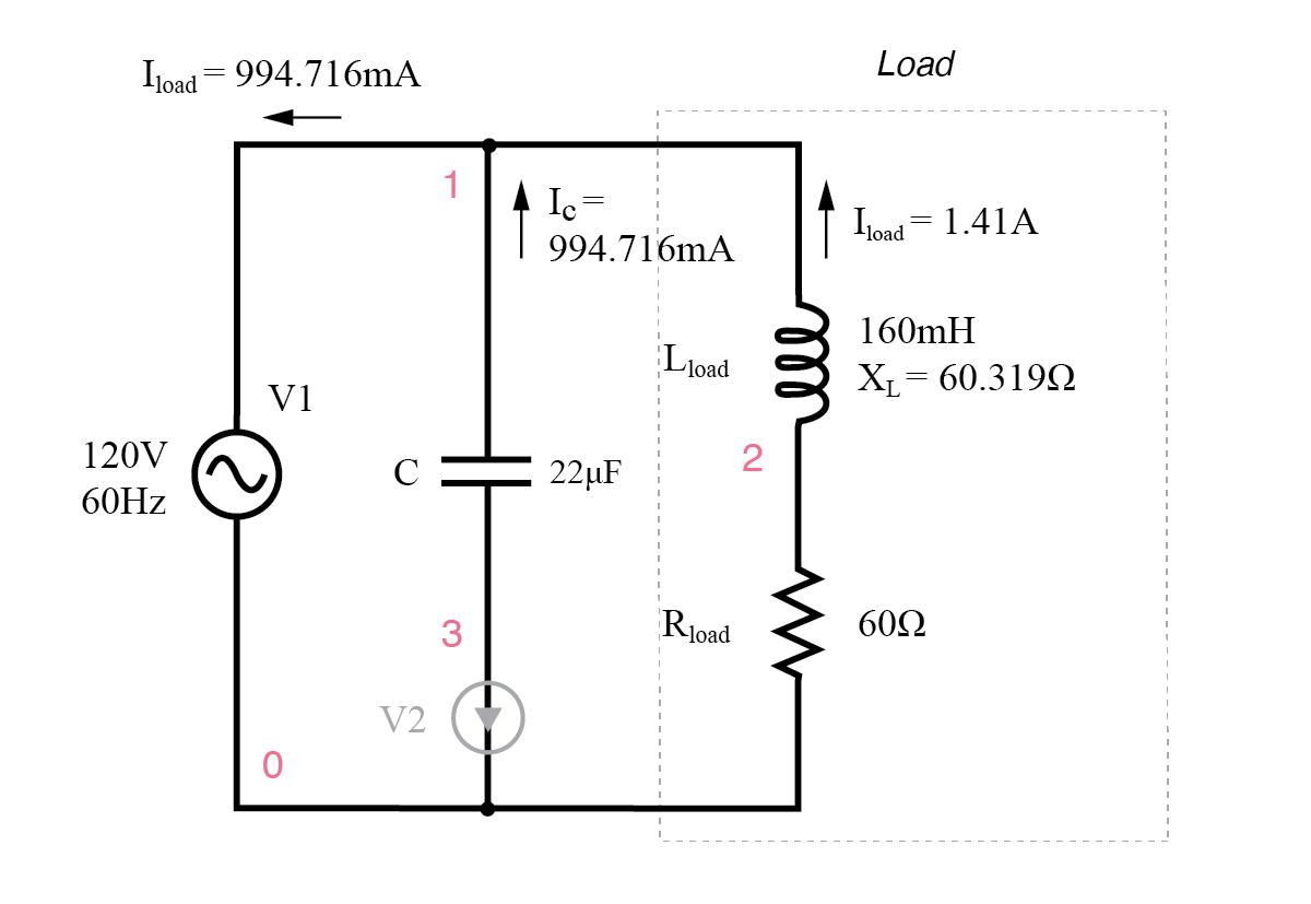
To restore PF close to 1, we add a reactive element that opposes the load’s reactance. Inductive loads are countered with capacitive reactance. In our example, a 22 µF capacitor in parallel with the source neutralizes the 119.998 VAR inductive reactive power.
The corrected circuit is shown below:
Results:
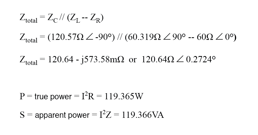
The total current drops from 1.410 A to 0.995 A while the resistive load continues to dissipate 119.365 W. The PF climbs from 0.705 lagging to 0.999 lagging, approaching unity.
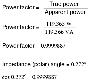
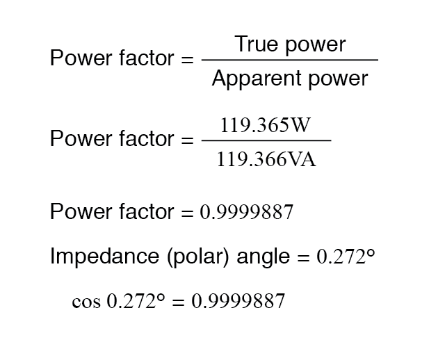
Although the corrected impedance angle remains slightly positive, indicating a residual inductive character, perfect correction would set the angle to zero. Over‑compensation would reverse the sign, yielding a leading PF.
Simulation and Practical Observations
The following SPICE netlist demonstrates the behavior of the corrected circuit. A zero‑voltage source (V2) is inserted in series with the capacitor to measure its current. The transient analysis starts at 200 ms to allow DC steady‑state conditions to settle.
Pf.cir
  V1 1 0 sin(0 170 60)
  C1 1 3 22uF v2 3 0 0
  L1 1 2 160mH
  R1 2 0 60
  .tran 1m 200m 160m
  .end
The Nutmeg plots reveal that the total current (Itotal) is now in phase with the applied voltage (Vtotal), confirming a near‑zero phase angle. The lagging inductor current is exactly counterbalanced by the leading capacitor current.
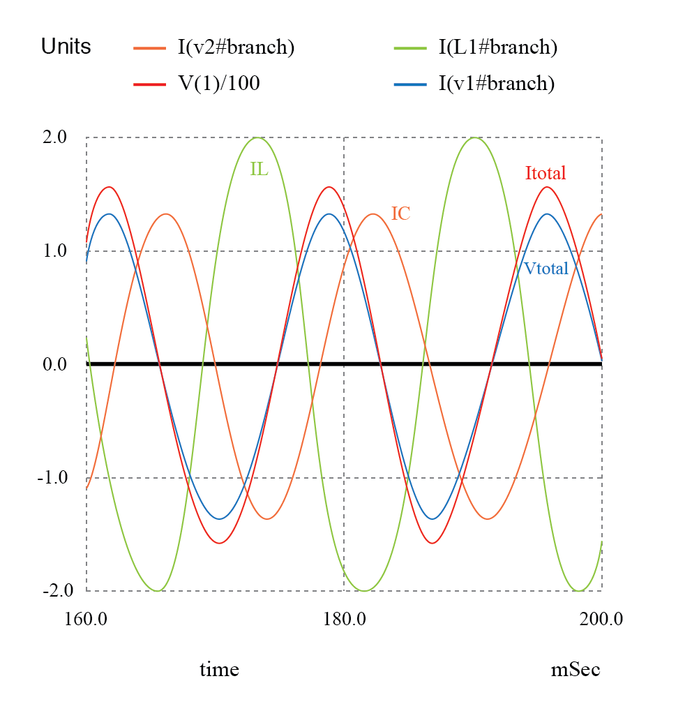
With the voltage and current in phase, the instantaneous power product is always positive, eliminating any back‑feed to the source. The reduction in line losses is significant, especially when the correction capacitor is placed close to the inductive load, such as an induction motor.
However, caution is required: adding too much capacitance can again degrade PF, and the capacitor must be rated for the system voltage, potential surges, and continuous AC operation.
In summary:
- A lagging PF indicates inductive dominance; a leading PF indicates capacitive dominance.
- PF correction is achieved by inserting a capacitor that supplies an equal but opposite reactive power to the inductive load.
- The goal is to bring the phase angle close to zero, yielding a PF near 1 and a more efficient power delivery.
Review
- Low PF can be remedied by adding a parallel reactance that opposes the load’s reactive component.
- Inductive loads are corrected with capacitors; the capacitor must be sized to generate the same magnitude of reactive power.
- Proper selection and placement of the capacitor minimize circulating currents and line losses.
Related Worksheet
For more on power factor correction, consult the IEEE Standard 1155 and IEC 60034 series.
Industrial Technology
- Constructing a Reliable Low‑Voltage AC/DC Power Supply: Bridge Rectifier & Capacitive Filter
- Calculating Electrical Power: Voltage, Current, and Resistance Explained
- Ensuring Electrical Safety: Grounding, Polarized Plugs, GFCIs, and AFCIs
- Understanding Q Factor and Bandwidth in Resonant Circuits: Theory, Calculations, and Practical Design
- Understanding Single‑Phase Power Systems: Efficiency, Safety, and Design
- Practical Guide to Power Factor Correction in AC Systems
- Quick & Accurate Brake Horsepower Calculation – Simple Formula & Step‑by‑Step Guide
- Low Power Factor Explained: Key Causes & How to Fix Them
- Why Power Factor Matters: Key to Efficient Electrical Systems
- Reliable Emergency Light Circuit: Expert Step‑by‑Step Guide