


Understanding Single‑Phase Power Systems: Efficiency, Safety, and Design
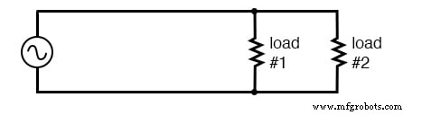
Illustration of a single‑phase power system. The schematic highlights key wiring considerations for real‑world applications.
Below is a very simple AC circuit. When the load resistor dissipates a substantial amount of power, we refer to this as a “power circuit” or “power system” rather than a generic circuit. The distinction may seem semantic, but the practical implications are significant.
Practical Circuit Analysis
In everyday engineering, the size and cost of wiring required to deliver power from the AC source to the load are critical. For educational circuits we often overlook this, but in real installations it can dominate the design budget.
Assigning a voltage to the source and power dissipation values to two load resistors allows us to calculate the necessary conductor specifications. For example:
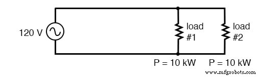
At 120 Vac, 20 kW loads draw 167 A total. This current demands at least 1/0‑gauge copper conductors.
1/0‑gauge wire is more than ¼ inch (6 mm) in diameter and weighs over 300 lb per thousand feet. Copper’s cost amplifies the total expense, especially over long distances.
A common cost‑saving strategy is to increase the supply voltage and use loads rated for the same power at the higher voltage. This reduces current, allowing the use of lighter, cheaper wire. For instance:
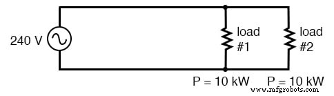
Two 10 kW loads at 240 Vac draw only 83 A total.
With half the current, 4‑gauge copper—lighter and cheaper—becomes sufficient, cutting system cost without sacrificing performance. This principle drives the use of high‑voltage transmission lines worldwide.
Risks of Higher Voltage
Elevated voltages increase the risk of electric shock, a concern that is rarely addressed in classroom examples but is paramount in practice. Distribution utilities mitigate this by suspending high‑voltage lines on tall towers with porcelain insulators. At the consumer level, maintaining a lower voltage (e.g., 120 V) keeps wiring out of reach and reduces shock potential.
European households operate at 240 V instead of 120 V. Tourists from the United States must carry step‑down transformers to power 120‑V appliances abroad—a practical illustration of the trade‑off between efficiency and safety.
Balancing Efficiency and Safety
Step‑Down Transformers at the Point of Use
Installing a transformer near the load can convert high‑voltage supply to a safer, lower voltage. While effective, this approach is costly and inconvenient for medium‑size loads.
Series‑Connected Low‑Voltage Loads
Another strategy is to supply two 120‑V loads in series from a 240‑V source. The total current remains 83 A, but each load sees only 120 V, improving safety while retaining the efficiency benefits of high voltage:
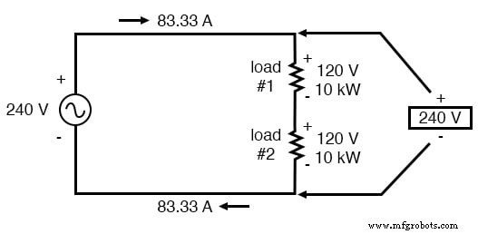
Two 120‑V loads in series powered by a 240‑V source. Current is 83 A, but each load operates at a safer voltage.
In this arrangement, the high‑voltage conductors still carry 240 V, but the risk of shock is concentrated on the lower‑voltage loads. An open or switched load will interrupt the entire circuit, so a neutral conductor is added to allow independent control:
Adding a neutral conductor permits individual load operation.
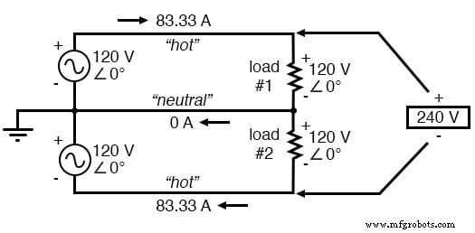
Split‑Phase Power Systems
A split‑phase system uses two 120‑V sources in phase, series‑connected to produce 240 V, and a neutral conductor to carry the difference in current between the two legs. With perfectly balanced loads, the neutral carries no current, yet it is grounded to ensure the lowest possible voltage relative to earth.
Most residential and light industrial systems in the United States are split‑phase, delivering 120/240 Vac. The dual AC source is typically produced by a center‑tapped transformer, as shown:
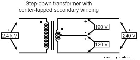
American 120/240 Vac power derived from a center‑tapped transformer.
Polarity markings (+ and –) are essential for clarifying phase relationships. Two 120‑V sources, phase‑aligned, can be represented as series‑aiding voltages, enabling clear mathematical treatment of voltage differences.
Split‑phase is a special case of single‑phase power, where multiple in‑phase AC waveforms share a common center tap. The term “single‑phase” refers to the fact that all voltage waveforms are in step, while “polyphase” denotes multiple, out‑of‑phase waveforms—a topic explored in later chapters.
Key Takeaways
- Single‑phase systems feature a single AC voltage waveform.
- Split‑phase systems use two in‑phase 120‑V sources in series to supply 240 V, balancing efficiency and safety.
- Center‑tapped transformers or alternator windings easily provide split‑phase supplies.
Related Worksheet
- Polyphase Power Systems Worksheet
Industrial Technology
- Constructing a Reliable Low‑Voltage AC/DC Power Supply: Bridge Rectifier & Capacitive Filter
- Common Failure Modes in Proven Electrical Systems
- Ensuring Electrical Safety: Grounding, Polarized Plugs, GFCIs, and AFCIs
- Three‑Phase Power Systems: Fundamentals and Benefits
- Understanding Harmonics in Polyphase Power Systems: Causes, Effects, and Mitigation Strategies
- Calculating Power Factor in AC Circuits: Theory, Impact, and Practical Correction
- Advanced Circuit Control & Protection Systems: Safeguarding Electrical Networks
- Single-Phase vs Three-Phase Power: Key Differences Explained
- Reliable Emergency Light Circuit: Expert Step‑by‑Step Guide
- UPS Circuit Design: Build Reliable Emergency Battery Backup Systems