


Three‑Phase Power Systems: Fundamentals and Benefits
What is Split‑Phase Power?
Split‑phase systems enhance conductor efficiency while reducing safety risks by dividing the total voltage into lower levels. Each load operates at a reduced voltage, yet the currents remain typical of a full‑voltage system.
While the term “phase” is strictly an AC concept, the same principle applies to DC. These are usually called three‑wire systems rather than split‑phase.
Because AC voltages that are out of phase do not simply add, we can exploit this behavior to create power systems with even greater conductor efficiency and lower shock hazards than split‑phase.
Examples
Two 120° Out of Phase Voltage Sources
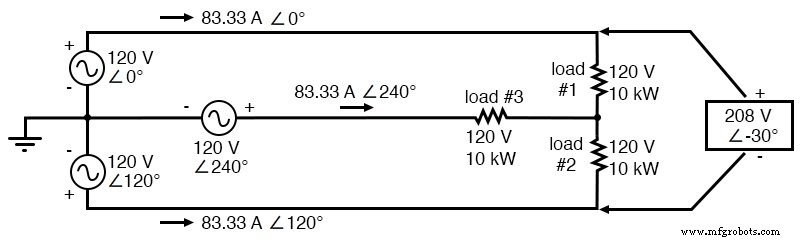
Consider two AC voltage sources connected in series as in a split‑phase system, but each source is 120° out of phase with the other:
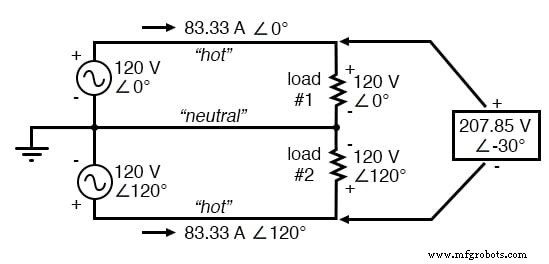
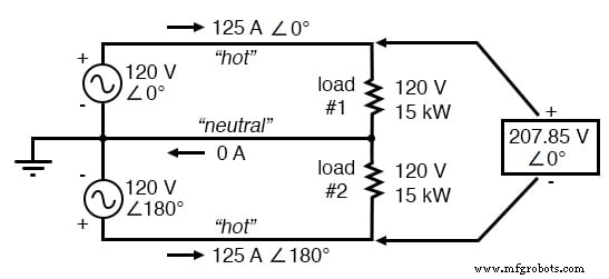
Pair of 120 Vac sources phased 120°, similar to split‑phase.
Each source supplies 120 V, and each load resistor is directly in parallel with its respective source. Consequently, the voltage across each load is 120 V, and with a load current of 83.33 A each load dissipates 10 kW.
The voltage between the two “hot” conductors is not 240 V (120° – 180°) because the phase difference is 120°. Instead, the line‑to‑line voltage is:
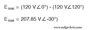
Nominally we say the voltage between the hot conductors is 208 V (rounded), so the system is designated as 120/208.
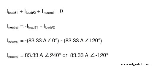
Calculating the neutral current reveals it is not zero even with balanced loads. Kirchhoff’s Current Law dictates that the currents entering and leaving the node between the two loads must cancel:
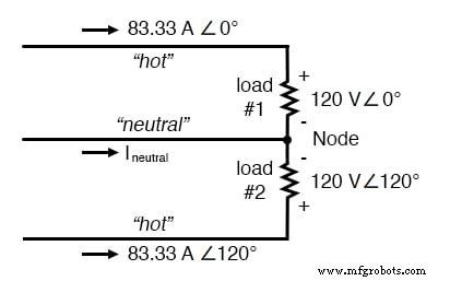
The neutral wire carries a full 83.33 A, just like each hot conductor.
Findings and Conclusions
Although the neutral still carries the same current as the hot conductors, the total power delivered remains 20 kW (10 kW per load). Because the hot‑to‑hot voltage is only 208 V—32 V lower than the split‑phase 240 V—safety is improved without changing conductor cost, since the same gauge copper is required.
Three 120° Out of Phase Voltage Sources
The neutral’s current suggests we could use it as an additional hot conductor. Adding a third 120‑V source 240° out of phase allows a fourth load to share the same three conductors:
With a third load phased 120° to the other two, the currents remain the same as for two loads.
SPICE Calculations for a Three‑Phase System
While a full network analysis would use the Superposition Theorem, the intuitive result is that three 120‑V sources 120° apart deliver 120 V to each balanced load resistor.
SPICE confirms this:
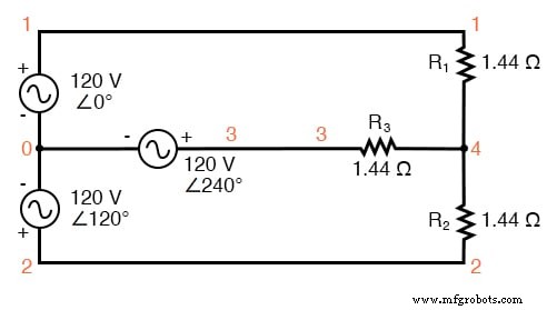
SPICE circuit: Three 3‑Φ loads phased at 120°.
120/208 polyphase power system v1 1 0 ac 120 0 sin v2 2 0 ac 120 120 sin v3 3 0 ac 120 240 sin r1 1 4 1.44 r2 2 4 1.44 r3 3 4 1.44 .ac lin 1 60 60 .print ac v(1,4) v(2,4) v(3,4) .print ac v(1,2) v(2,3) v(3,1) .print ac i(v1) i(v2) i(v3) .end
VOLTAGE ACROSS EACH LOAD freq v(1,4) v(2,4) v(3,4) 6.000E+01 1.200E+02 1.200E+02 1.200E+02 VOLTAGE BETWEEN “HOT” CONDUCTORS freq v(1,2) v(2,3) v(3,1) 6.000E+01 2.078E+02 2.078E+02 2.078E+02 CURRENT THROUGH EACH VOLTAGE SOURCE freq i(v1) i(v2) i(v3) 6.000E+01 8.333E+01 8.333E+01 8.333E+01
Results show 120 V across each load, ~208 V between any two hot conductors, and 83.33 A in each conductor. Each load thus dissipates 10 kW.
The circuit lacks a neutral wire for voltage stability. If one load opens, the remaining loads see altered voltages. Adding a neutral ensures stable operation when loads are balanced, and it carries no current unless a load fails or is disconnected.
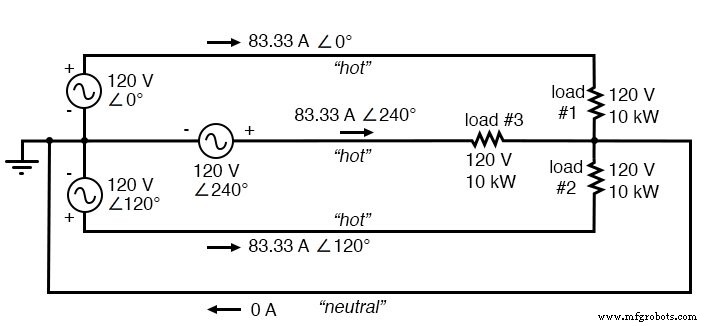
SPICE circuit annotated with simulation results: Three 3‑Φ loads phased at 120°.
Polyphase Circuit
What we’ve examined—three voltage sources with distinct phase angles—is called a polyphase circuit. The prefix “poly” means “more than one,” as in “polytheism” or “polygon.” In power systems, it denotes multiple phase‑shifted voltage waveforms.
Specifically, a three‑phase circuit is the most common form of polyphase system, powering large‑scale distribution networks.
Three‑Phase System vs. Single‑Phase System
Single‑Phase System
Three identical loads on a single‑phase 120 V system draw a total of 250 A (83.33 A × 3). To handle this current, 3/0 AWG copper (≈510 lb/1,000 ft) would be required. Over 1,000 ft, more than half a ton of copper would be needed.
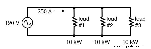
For comparison, three 10 kW loads on a 120 Vac system draw 250 A.
Split‑Phase System
A split‑phase system can halve the current. Two 15 kW, 120 V loads draw 125 A at 240 V line voltage, allowing use of 2 AWG copper (≈200 lb/1,000 ft). However, the presence of 240 V introduces a higher shock risk.
Split‑phase system draws half the current of 125 A at 240 Vac compared to 120 Vac system.
Three‑Phase System
Compared to the previous two, a balanced three‑phase system uses only 83.33 A per conductor. 4 AWG copper (≈125 lb/1,000 ft) suffices, cutting material cost while keeping the maximum voltage at 208 V—lower than the 240 V in split‑phase.
The main question is how to generate three AC voltage sources 120° apart. Unlike split‑phase, which uses a center‑tap, a three‑phase alternator places three winding sets 120° around the rotor, producing the required phase shift directly at the source.
In the figure below, the six pole windings form three pairs; each pair delivers a 120‑V AC waveform 120° out of phase with the others. The windings are typically wired in a “Y” (star) configuration, connecting one end of each winding to a common neutral node.
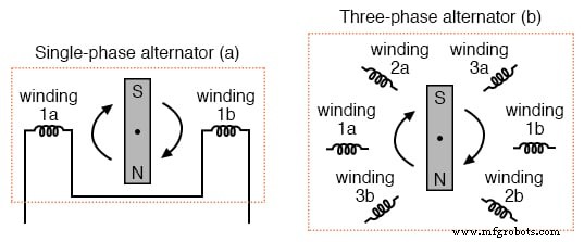
(a) Single‑phase alternator, (b) Three‑phase alternator.
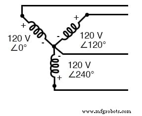
Alternator Y configuration.
Review
- A single‑phase system has one AC voltage source.
- A split‑phase system uses two 180° out‑of‑phase sources, reducing conductor currents while keeping load voltages low.
- A polyphase system employs multiple voltage sources with different phase angles, delivering more power at lower voltage and with smaller conductors.
- Phase‑shifted voltage sources are created in alternators with multiple winding sets spaced around the rotor.
Related Worksheets
- Polyphase Power Systems Worksheet
Industrial Technology
- PWM Power Controller: Build a Pulse‑Width Modulated Lamp Driver
- Power Supply Circuits: Types, Design Principles, and Performance
- Understanding Power in Electric Circuits: Measurement & Significance
- Voltage Signal Systems: Accurate Measurement of Water Tank Levels
- Understanding Single‑Phase Power Systems: Efficiency, Safety, and Design
- Three‑Phase Y and Delta Configurations: Design, Analysis, and Reliability
- Understanding Harmonics in Polyphase Power Systems: Causes, Effects, and Mitigation Strategies
- Accurate Power Measurement in AC Circuits: From Electrodynamometers to Hall‑Effect Sensors
- Understanding Flicker: Impact on Power Quality and How Variable Speed Drives Help
- Three-Phase Power Explained: Delivering Stable, Efficient Electrical Energy