


Voltage Signal Systems: Accurate Measurement of Water Tank Levels
Using variable voltage for instrumentation signals is a well‑established approach. In the following example, a voltage‑based transmitter and indicator system demonstrates how water‑tank levels can be monitored accurately.
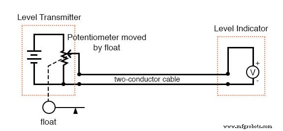
The transmitter houses a precision‑regulated voltage source. A float inside the tank moves with the water level, adjusting a potentiometer that divides the source voltage. The resulting voltage is sent over a two‑conductor cable to an indicator—a calibrated voltmeter that translates voltage into a physical height (inches, feet, meters).
As the tank fills or empties, the float’s motion changes the potentiometer’s wiper position. Consequently, the proportion of the source voltage reaching the indicator varies, providing a real‑time representation of the tank’s level.
While this transmitter/indicator arrangement is straightforward and reliable, it has a key limitation: cable resistance. Even ideal voltmeters draw a tiny current, especially the rugged analog meters used in industrial settings. This current, passing through the cable’s inherent resistance, causes a voltage drop that can reduce the signal seen at the indicator, introducing a measurement error.
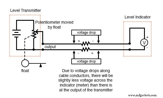
Resistor symbols illustrate this effect in a real system. To mitigate the error, one can use heavy‑gauge wire (at extra cost) or a high‑resistance (null‑balance) voltmeter at the indicator (at additional complexity).
Despite this drawback, voltage signals remain popular because of their design simplicity. Common standards include 0‑10 V, where 0 V equals 0 % measurement, 10 V equals 100 %, and 5 V equals 50 %. Many manufacturers supply instruments that both output and accept this range. A 1‑5 V range is also common, employing a “live‑zero” concept that flags circuit faults.
Review:
- DC voltage can serve as an analog signal to transmit information between locations.
- Voltage signaling’s main drawback is the potential drop along the cable, caused by resistance and indicator current draw, which creates measurement error between source and indicator.
Industrial Technology
- Exploring Voltage Addition with Series Battery Connections
- Voltage Divider Lab: Design, Measurement, and Kirchhoff’s Voltage Law Verification
- Signal Coupling: Understanding AC Noise in Telephone Cables
- Understanding Logic Signal Voltage Levels: TTL vs CMOS
- Voltage‑to‑Current Signal Conversion: A Practical Transconductance Amplifier Design
- Current Signal Systems: The 4‑20 mA Loop Explained
- Tachogenerators: Precision Speed Measurement for Industrial Motors and Equipment
- Understanding AC Waveforms: Sine Waves, Frequency, and Oscilloscope Basics
- Three‑Phase Power Systems: Fundamentals and Benefits
- Build a Reliable LED Voltage Indicator: 4 Simple DIY Projects