


Current Signal Systems: The 4‑20 mA Loop Explained
Current Source Fundamentals
By leveraging electronic amplifiers, a circuit can be designed to deliver a constant current regardless of the voltage required across its terminals. Such assemblies are collectively referred to as a current source, and its schematic symbol is shown below:
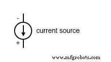
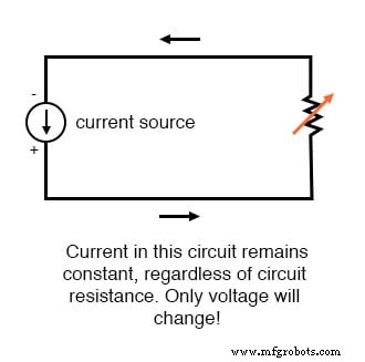
A current source maintains a fixed current, adjusting the voltage as necessary to preserve that current through its load. This is the logical counterpart of an ideal voltage source (a perfect battery), which keeps its voltage constant while allowing the current to vary in response to the external circuit.
Modern instrumentation often employs variable current sources, enabling highly accurate and reproducible signal levels. Replacing a variable voltage source with a variable current source in a transmitter design yields a signal system that operates on current rather than voltage:
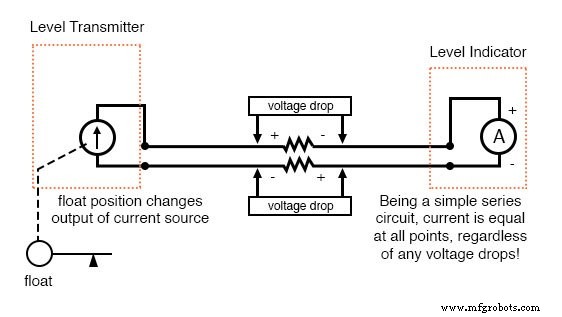
The transmitter’s internal circuitry is secondary to its external behavior: the output current changes proportionally with the float position, mirroring how a potentiometer in a voltage system adjusts voltage output.
In this configuration the indicator is an ammeter rather than a voltmeter, with its scale calibrated to reflect the water level in inches, feet, or meters. Because the loop is a series circuit, current remains identical across every component—cable resistance included—ensuring the current measured at the indicator equals the current generated at the transmitter. This eliminates the signal‑degradation that can plague voltage‑based systems and is a primary advantage of current‑loop signalling.
The 4‑20 mA Current Loop
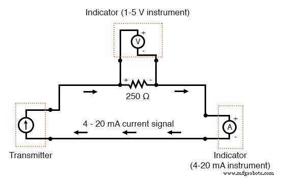
The industry‑standard current loop is 4 to 20 mA. In this range, 4 mA represents 0 % of the measured quantity, 20 mA represents 100 %, and intermediate values correspond linearly (e.g., 12 mA equals 50 %). A key benefit of the 4‑20 mA standard is its straightforward conversion to a 1‑5 V signal: a precision 250‑Ω resistor in series produces a voltage drop of 1 V at 4 mA, 5 V at 20 mA, and proportional values in between.
| Percent of Measurement | 4‑20 mA Signal | 1‑5 V Signal |
|---|---|---|
| 0 | 4.0 mA | 1.0 V |
| 10 | 5.6 mA | 1.4 V |
| 20 | 7.2 mA | 1.8 V |
| 25 | 8.0 mA | 2.0 V |
| 30 | 8.8 mA | 2.2 V |
| 40 | 10.4 mA | 2.6 V |
| 50 | 12.0 mA | 3.0 V |
| 60 | 13.6 mA | 3.4 V |
| 70 | 15.2 mA | 3.8 V |
| 75 | 16.0 mA | 4.0 V |
| 80 | 16.8 mA | 4.2 V |
| 90 | 18.4 mA | 4.6 V |
| 100 | 20.0 mA | 5.0 V |
The 4‑20 mA loop has become the dominant standard for analog current signalling, largely due to its safety profile. Compared with the older 10‑50 mA range, the lower voltage and current levels reduce the risk of electric shock and spark generation in hazardous industrial environments, aligning with IEC/ISA safety guidelines.
Key Takeaways
- A current source delivers a steady current, analogous to how a voltage source maintains a steady voltage.
- In a current‑loop system, series wiring guarantees identical current through all components, eliminating errors from cable resistance.
- The 4‑20 mA loop remains the prevailing analog current standard in industrial instrumentation.
Industrial Technology
- Hands‑On Guide to Current Dividers: Build, Measure, and Simulate with a 6 V Battery
- Understanding Numeration Systems: Roman, Place Value, Binary
- Common-Emitter Amplifier Limitations: Distortion, Temperature, and High‑Frequency Challenges
- Insulated‑Gate Bipolar Transistors (IGBTs): Merging FET Precision with BJT Power
- DIAC: The Bidirectional Trigger for AC Thyristors
- Voltage‑to‑Current Signal Conversion: A Practical Transconductance Amplifier Design
- Understanding Electrical Resistance and Circuit Safety
- Understanding Meter Design: From Classic Galvanometers to Modern Digital Displays
- Voltage Signal Systems: Accurate Measurement of Water Tank Levels
- Branch Current Method: A Step‑by‑Step Guide to Solving Circuit Networks