


Voltage‑to‑Current Signal Conversion: A Practical Transconductance Amplifier Design
In modern instrumentation, DC signals serve as analog proxies for physical variables such as temperature, pressure, flow, weight, and motion. The industry’s preferred format is a DC current signal—typically 4 mA to 20 mA—because current remains uniform throughout a series loop, irrespective of wire resistance. In contrast, voltage signals can drift along a parallel circuit, introducing measurement errors.
To generate a precise current from a voltage‑driven transducer, we employ a transconductance amplifier—an op‑amp configured with negative feedback that behaves as an ideal current source. The op‑amp supplies whatever voltage is necessary to keep the loop current at a fixed value, regardless of the load resistance.
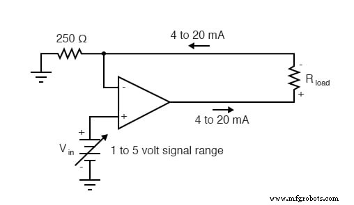
The input is a calibrated voltage from 1 V (0 % measurement) to 5 V (100 % measurement). The circuit uses a precision 250 Ω resistor to translate that voltage into the standard 4 mA–20 mA current range: at 5 V, 20 mA flows through the loop, and at 1 V, 4 mA flows. The load resistance can be any value, and the op‑amp will adjust its output voltage accordingly—provided its supply voltage is sufficient to drive the required current. If an older 10 mA–50 mA standard is needed, a 100 Ω resistor replaces the 250 Ω component.
In electronics, transconductance is the ratio ΔI/ΔV, measured in Siemens. In this design, the 250 Ω resistor fixes the transconductance, ensuring a linear current‑out/voltage‑in relationship.
Key Takeaways
- Current signals dominate industrial instrumentation because they are immune to wire resistance and provide consistent, accurate transmission.
- Voltage signals are easier to generate directly from sensors, but converting them to current requires a stable transconductance amplifier.
- An op‑amp configured as a current source supplies the exact voltage needed to maintain the desired loop current.
Related Worksheet
- Voltage/Current Converter OpAmp Circuits Worksheet
Industrial Technology
- Signal Coupling: Understanding AC Noise in Telephone Cables
- Understanding Logic Signal Voltage Levels: TTL vs CMOS
- Understanding Voltage and Current: The Foundations of Electrical Flow
- Voltage Signal Systems: Accurate Measurement of Water Tank Levels
- Current Signal Systems: The 4‑20 mA Loop Explained
- Understanding Insulator Breakdown Voltage and Dielectric Strength
- Capacitors & Calculus: How Voltage Change Drives Current
- Understanding AC Inductor Circuits: Reactance, Phase Shift, and Power Dynamics
- AC Capacitor Circuits: Capacitive Reactance, Phase Shift, and Power Behavior
- Understanding Characteristic Impedance in Transmission Lines