


Understanding Voltage and Current: The Foundations of Electrical Flow
Before electrons can move, a circuit must exist, but that alone isn’t enough. A force—just as a push is required to launch a marble—drives charge carriers through a conductor. In static electricity, this force stems from an imbalance of electric charge: one body gains electrons (negative) while another loses them (positive). When a conductive wire bridges the charged objects, electrons flow from the surplus to the deficit, temporarily neutralizing the imbalance.
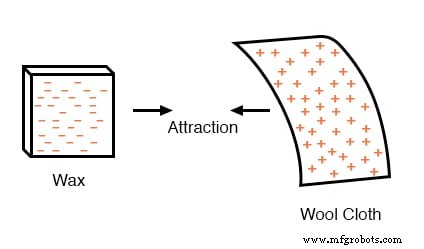
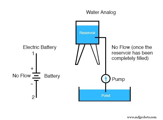
Once a conductor connects the two bodies, the electric field forces electrons to move until the charges balance again. This process releases stored energy, analogous to water released from a pumped reservoir.
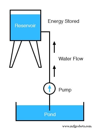
In both cases—electrons or water—the energy is stored as potential energy. When a pathway is opened, that stored energy converts to kinetic energy: a sudden shock when touching a doorknob or a surge of water flowing back down.
What Is Voltage?
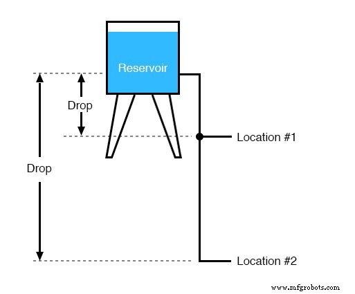
Voltage is the measure of potential energy per unit charge. It quantifies the “push” required to move a charge from one point to another against the restoring electric force. Like the height difference between two levels of a reservoir, voltage is always defined between two points; it cannot be stated in isolation.
Generating Voltage
Voltage arises from various sources: chemical reactions (batteries), photovoltaic conversion (solar cells), and electromagnetic induction (generators). Each creates a potential difference that drives charge carriers when a complete circuit is present.
How Batteries Work
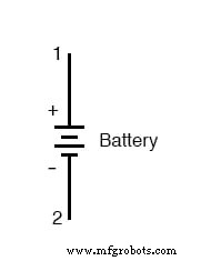
A battery has two terminals: the positive (+) end, marked by the longer horizontal line, and the negative (–) end, marked by the shorter line. Internally, the battery’s electrolyte allows ions to move, creating a potential difference between the plates. When a wire connects the terminals, electrons flow from the negative to the positive side, establishing a continuous current.
Electric Current
With voltage applied and a closed loop, charge carriers move uniformly in one direction—this is direct current (DC). The current’s magnitude is the same at every point in a single‑loop circuit, just as the number of marbles passing through any cross‑section of a pipe remains constant.
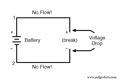
Breaking the circuit anywhere stops the flow entirely; the full battery voltage then appears across the open gap.
Polarity of a Voltage Drop
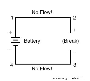
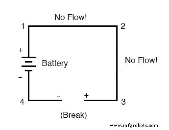
Polarity is the sign (+ or –) assigned to a point relative to another. For a given voltage source, the positive terminal is the higher potential, and the negative is lower. In a circuit, the polarity of a drop between two points depends on the direction of the applied voltage. For example, if the circuit is open between points 2 and 3, point 2 is + and point 3 is –; if the break is between points 3 and 4, the labels swap.
Review
- Charge carriers move under the same force that produces static electricity.
- Voltage measures specific potential energy (energy per unit charge) between two points.
- Voltage is always relative; it’s sometimes called a voltage drop.
- When connected to a circuit, a voltage source creates a uniform flow of charge—a current.
- In a single loop, the current is identical at every point.
- Breaking a voltage‑sourced circuit makes the full source voltage appear across the gap.
- Polarity (+/–) is relative between two points.
Related Worksheets
- Voltage, Current, and Resistance Worksheet
Industrial Technology
- Understanding Electrons, Holes, and Doping in Semiconductors
- Voltage and Current in a Practical Circuit: Understanding Their Relationship
- Ohm’s Law Explained: How Voltage, Current, and Resistance Interact in Electrical Circuits
- Understanding Insulator Breakdown Voltage and Dielectric Strength
- Capacitors & Calculus: How Voltage Change Drives Current
- Calculating Voltage and Current in Reactive DC Circuits
- Advanced Analysis of DC Reactive Circuits with Non‑Zero Initial Conditions
- Understanding AC Inductor Circuits: Reactance, Phase Shift, and Power Dynamics
- AC Capacitor Circuits: Capacitive Reactance, Phase Shift, and Power Behavior
- Understanding Mutual Inductance and Transformer Fundamentals