


High‑Performance Variable Voltage & Current Power Supply – Stable Output for Lab and Industrial Use
An ideal power supply unit must feature a variable voltage and current power supply circuit. The property is most important in common laboratory uses and in various applications that require AC voltage regulation.
A voltage regulator with manipulatable current limits facilitates the generation of the desired output current.
Thus, for this reason, we will be looking at ways of creating a variable power supply circuit. Further, we’ll look at simple ways of regulating the output voltage and features of the circuit.
Hence, read on for a thorough elaboration on this circuit and how an adjustable voltage regulator works.
Features of the Circuit
Figure 1: A Technician connecting a circuit
Here is a list of some of the features of a variable voltage control system.
- It has a wide power supply voltage range which is adjustable. It has several voltage ranges of 0 to 30V, 0 to 60V, or 0 to 100V. You can also adjust the load current from 500mA to 10 Amp. Thus, the minimum output voltage depends on the preferences of the user.
- The circuit is also not prone to short-circuiting, especially when you connect heat sinks.
- It also does not have ripple voltage since it features ripples of less than 1Vpp.
- It features a stable current at the output stage. The circuit will filter the AC power supplies to a direct current.
- The circuit can also not suffer from an overload.
- Lastly, it features a short-circuit power display in the form of a LED.
The Circuit Design
Figure 2: Electrical Supplies
Let us now look at the various designs of a variable voltage regulator. First, it’s noteworthy that there are several designs of a current regulator, and we shall therefore have an in-depth look at each of the standard power supply systems.
Using Transistor 2N3055
Here is the circuit diagram of this circuit.
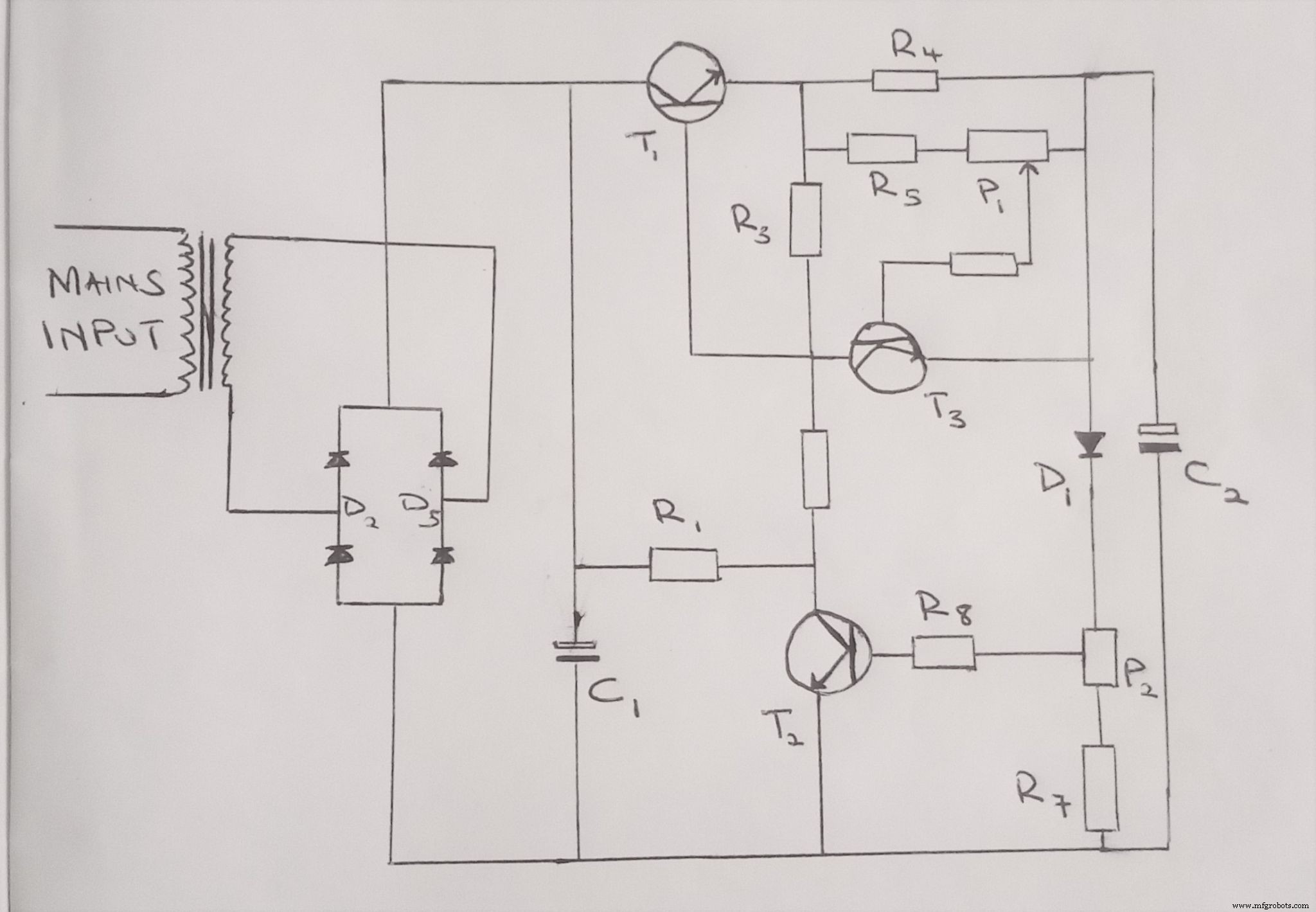
Figure 3: A Variable Voltage and Current Power Supply Circuit Diagram
As you can see from the above depiction, it is typically a stable power supply unit that delivers on the above-listed features.
The presets in the circuit are responsible for the creation of the voltage variations. They facilitate this via a feedback configuration by the transistors, resistors, and diodes in the course.
From the diagram, you can identify the diode denoted as D1. The diode is responsible for lowering the current up to 0.6V, and the figure is the diode’s forward voltage drop.
Assume you are looking for a constant voltage that is below 0.6V or any other value. In such a case, you have to replace the diode D1 with a Zener diode that gives the preferred value. You will thus control current limiting by choosing the ideal diode.
In this circuit, the transformer has a range of 0 to 40V. Hence, the adjustable output voltage of the course will be from 0.6V to 40V. Therefore, for quality power supplies, your power transformer must have the desired output range.
Also, note that the transistor in this circuit will operate as a current limiter. Hence, you must also use the right one to achieve the maximum output current that you want.
Figure 4: DIY Electronics on a Breadboard
For a PCB board design, here are some of the electronic devices that you require to assemble the circuit:
A 0-40V Transformer
Two capacitors of 1000uF/50V
Four 1N5402 diodes
A 1N4007 diode
Two BC547B transistors
A 2N3055 transistor
Resistors
A 5-watt wire
Using 2N3055 and 2N2222 Transistors
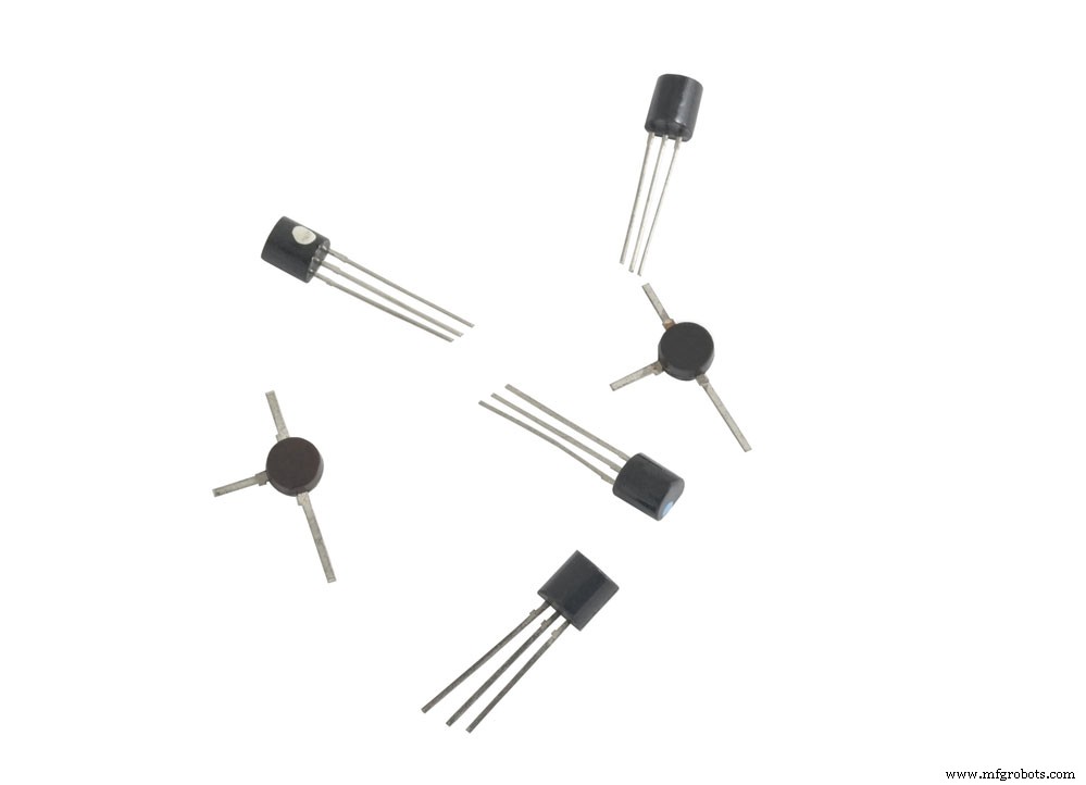
Figure 5: Transistors
You can also use 2N3055 and 2N2222 Transistors together to improve the circuit. One of the fundamental highlights of this circuit is that it features a wide range of output. Thus, it can supply constant current at a range of 0.1 to 50 volts. Hence, it has an efficient load regulation.
Also, the circuit features a minimal output disturbance. As earlier mentioned, the simple power supply has a broad output range, and an integrated circuit facilitates this property.
You can further improve the output range by introducing a transistor. Position this electrical device in series with the IC and series pass transistor.
Using LTC3780

Figure 6: A Power Supply Unit
The circuit, like the previous one, will deliver an output adjustable between 0 to 30V. Also, the course will have an electronic output current limiter that will control the range of deliverable current. Due to this property, the circuit is useful in a current lab power supply system.
You can quickly increase the current to a maximum value without worrying about the safety of the components. Additionally, the variable feature facilitates a current supply in line with the circuits’ power supply specifications.
Here are some of the technical specifications of the circuit:
- The input voltage is at 24 VAC.
- It has a maximum input current of 3A.
- It features an output voltage range of between zero to a maximum of 30V.
- The current output is also adjustable and ranges from 2mA to 3A.
- Its output voltage ripple is at a maximum of 0.01 %.
- Lastly, the ideal PCB dimensions are 123mm by 85 mm.
Using LM317T
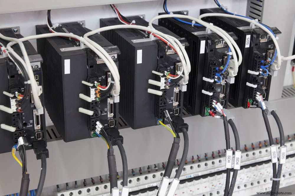
Figure 7: Several Electrical Components
In this circuit, the LM317T will operate as a positive voltage regulator capable of delivering various DC voltages. Without the regulator, the course would supply a fixed power supply. Nonetheless, the addition of the integrated circuit facilitates the creation of a wide range of output voltages.
Therefore, the voltage regulator will create a variable voltage ranging from 1.25V to a maximum of approximately 30V.
The regulator also features a current-limiting property, and it also has a thermal shut down property. Hence, it cannot quickly short-circuit. As a result, you can use it for a low voltage supply.
Determining the output voltage of the system is also easy. All you require is to have the voltages of the two feedback resistors of the system, and the resistors create a potential divider at the output of the circuit.
Variable Voltage and Current Power Supply Circuit– How to create the circuit?
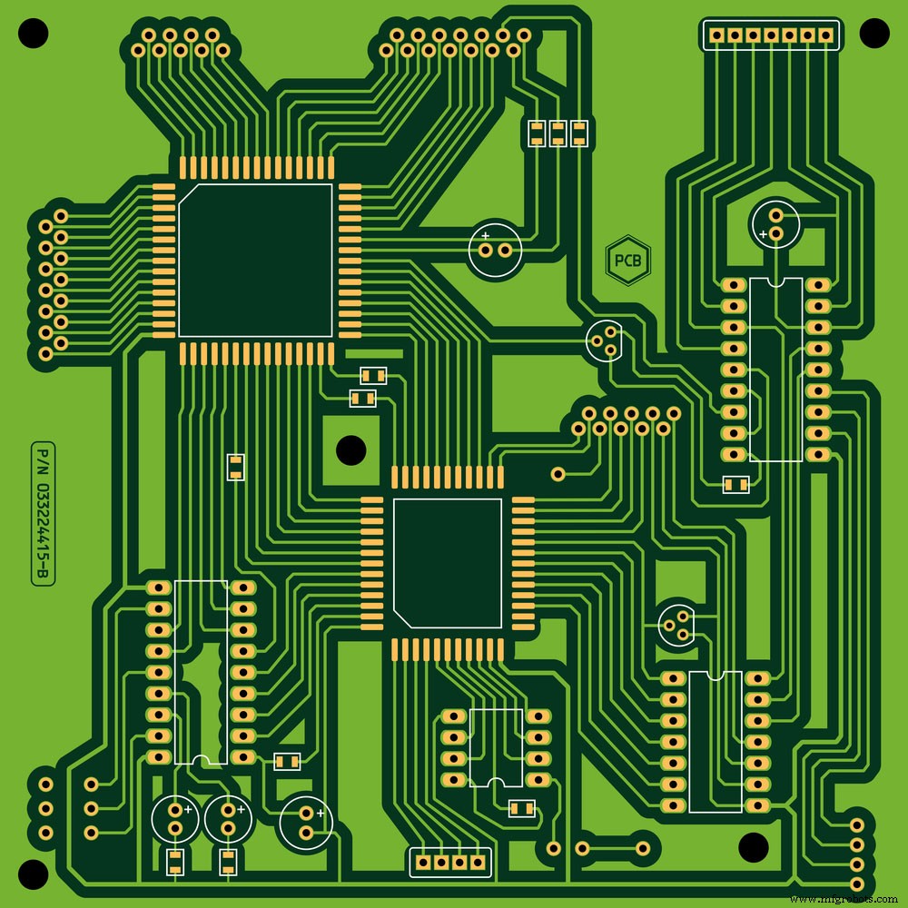
Figure 8: A Printed Circuit Board (PCB)
For electronic circuits with a variable voltage range, you will require the following components.
- An adjustable voltage convertor. Ideally, an LTC3780 is the best.
- A digital potentiometer or ammeter
- Two linear potentiometers featuring 500k and 200k
- A 7805 IC
- A 12V 3A Adapter
- Two capacitors with capacitances of 100uF and 10uF
- A rectifier diode
- A direct current switch
- Heat sink
- Several wooden blocks
- A PCB board
- A 4mm Acrylic Sheet
- Enough wires
- A 2.1mm DC Jack Connect
It would help if you also had some tools in place to make the circuit. Here is a list of the tools that you need to assemble.
- A strong superglue
- A handsaw
- Spray paint of your preferred color
- Soldering iron
- Sandpaper
- Glue gun
- Masking tape
- A rotary tool and a drill
Variable Voltage and Current Power Supply Circuit– How to Assemble the Circuit

Figure 9: A Variable Voltage Circuit Board with Components
In a few simple steps, you can quickly assemble the circuit. Let’s look at each one of them.
- First, draw lines on the acrylic sheet to mark where you will cut it. Next, cut the sheet along the lines that you have drawn.
- Next, mark where you will have the potentiometer, air passing, the socket, and the DC fan. Cut these areas using the ideal tool for each task.
- Next, you need to sand the acrylic sheet. In this step, you’ll first need to peel the paper cover of the sheet. After this, grind it efficiently until you obtain a flat surface.
- The next thing is to attach the sheets along the edges. First, apply glue to the sides and connect the sheets next to each other. The drawings that you have previously made on the sheet should guide you in this process.
- After attaching the parts, it’s now time to paint the sheets. Apply a thin layer of your color of choice. Black is ideal, but you can choose the color you wish to apply depending on your preferences.
- You will then need to attach the extra pieces of acrylic to the system. They are essential in the attachment of screws.
- After this, attach the front and the back panels. You will have to apply superglue first. Next, quickly place the panels onto the area where the glue is before it dries off.
- Next, mount the components. First, mount the DC switch, then attach the DC fan using a screw. Similarly, connect the other parts.
Variable Voltage and Current Power Supply Circuit–Temperature Control in the Circuit
- You must also be keen on controlling the temperature of the power supply. Therefore, you will require to connect a heatsink and a fan. The LTC3780 voltage convertor should have an inbuilt heat sink. Nonetheless, to improve its efficiency, consider adding one.
- Replace the inbuilt potentiometer with a linear potentiometer. The process is easy. Simply replace the trimmer potentiometer with the liner one by soldering it on the exact points.
- Lastly, connect the wires to complete the circuit.
Conclusion
In a nutshell, we have provided you with a detailed explanation of how a variable voltage and current power supply circuit works. We have also elaborated on how to create a simple course using easy to assemble components.
We are also here to assist you in case you have any questions about the circuit. Reach out to us and visit our blog for further insights on courses.
Industrial Technology
- Essential DC Circuit Equations and Laws for Engineers
- Power Supply Circuits: Types, Design Principles, and Performance
- Understanding Voltage and Current: The Foundations of Electrical Flow
- Voltage and Current in a Practical Circuit: Understanding Their Relationship
- Capacitors & Calculus: How Voltage Change Drives Current
- Advanced Analysis of DC Reactive Circuits with Non‑Zero Initial Conditions
- Mastering Current, Power, and Torque in Variable Speed Drives
- Build a Custom Variable Power Supply with Arduino UNO – Step‑by‑Step Circuit & Code
- Precise Power Measurement Using Digital and Analog Multimeters
- Overvoltage Protection Circuits: Types, Functionality, and DIY Projects for Reliable Power Supply