


Understanding AC Inductor Circuits: Reactance, Phase Shift, and Power Dynamics
Resistors vs. Inductors
Inductors behave quite differently from resistors. A resistor simply drops a voltage that is proportional to the current flowing through it. In contrast, an inductor resists changes in current by generating a voltage proportional to the rate of change of that current. This relationship is governed by Lenz’s Law, which ensures the induced voltage always acts to maintain the current at its present value.
When current rises, the induced voltage opposes the increase; when current falls, the polarity reverses and the voltage assists the decrease. This opposition to current change is called reactance, not resistance. The governing equation is:

Alternating Current in a Simple Inductive Circuit
In AC analysis, di/dt denotes the instantaneous rate of change of current (amps per second). Inductance (L) is measured in Henrys, and the induced voltage (v or e) is in volts. The fundamental relationship for an inductor is v = L·di/dt.
Consider a pure inductive circuit driven by a sinusoidal source:
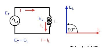
Pure inductive circuit: Inductor current lags voltage by 90°.
The voltage and current waveforms are 90° out of phase:
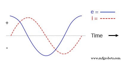
Waveforms in a pure inductive circuit.
Because the induced voltage depends on the rate of change of current, the voltage is zero at the peaks of the current waveform (where the slope is zero) and reaches its maximum when the current slope is steepest.
This phase relationship means the voltage leads the current by 90°, and the current lags behind the voltage.
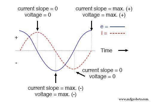
Voltage leads current by 90° in a pure inductive circuit.
Instantaneous Power and Negative Power
Instantaneous power is the product of instantaneous voltage and current (p = v·i). In a pure inductive circuit, this product oscillates between positive and negative values because voltage and current are 90° out of phase.
When voltage and current share the same sign, power is positive—indicating energy absorption. When they have opposite signs, power becomes negative, meaning the inductor returns energy to the circuit. Over a full cycle, the positive and negative areas cancel, so the net energy exchange is zero (ideal inductors have no resistive losses).
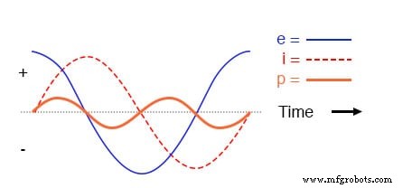
Instantaneous power oscillates between positive and negative.
Reactance vs. Resistance
While both resistance and inductive reactance oppose current, reactance introduces a phase shift and dissipates no net power. Reactance is measured in ohms and denoted by X, whereas resistance uses R.
For inductors, reactance is represented as X_L and calculated by:
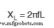
Here, f is frequency (Hz) and ω = 2πf is angular velocity in radians per second. Because reactance scales with frequency, higher‑frequency signals encounter greater opposition from the same inductor.
For example, a 10 mH inductor exhibits the following reactances:
Reactance of a 10 mH Inductor
| Frequency (Hz) | Reactance (Ω) |
|---|---|
| 60 | 3.77 |
| 120 | 7.54 |
| 2500 | 157.08 |
Angular Velocity in AC Systems
Angular velocity, denoted by ω (omega), represents the rate of change of the AC waveform in radians per second. It equals 2πf and is distinct from the mechanical shaft speed of the generator producing the AC.
In multi‑pole alternators, ω can be several times the shaft speed, so it is often expressed in electrical radians per second to avoid confusion.
Phase Angles and Complex Representation
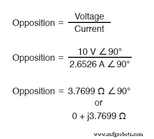
Because voltage and current are not in phase, it is convenient to express the inductor’s opposition as a complex quantity. The impedance of an ideal inductor is Z_L = jX_L = jωL, where j indicates a 90° phase lead for voltage over current.
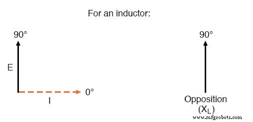
Current lags voltage by 90° in an inductor.
Using complex notation simplifies the analysis of AC circuits that include both resistive and reactive components, allowing straightforward calculation of magnitudes and phase relationships.
Review
- Inductive reactance is the opposition an inductor presents to AC due to its magnetic field storage, measured in ohms and denoted by
X. - It is calculated with
X_L = 2πfL. - Angular velocity
ω = 2πfdescribes the waveform’s speed in radians per second. - Inductive reactance increases with frequency, meaning higher‑frequency signals experience greater opposition.
Related Worksheets
- Inductors Worksheet
- Inductive Reactance Worksheet
Industrial Technology
- Using Commutating Diodes to Protect Inductive Loads
- Power Supply Circuits: Types, Design Principles, and Performance
- Understanding Power in Electric Circuits: Measurement & Significance
- Voltage Divider Circuits: Mastering Series Resistor Analysis & Potentiometers
- Understanding Insulator Breakdown Voltage and Dielectric Strength
- Understanding Inductor Transient Response: Energy, Current, and Voltage Dynamics
- Understanding Instantaneous Values in Pure AC Resistor Circuits
- Analyzing Series Resistor‑Inductor AC Circuits: Impedance, Phase, and SPICE Verification
- Pure Resistive AC Circuits: Voltage and Current In Phase
- AC Capacitor Circuits: Capacitive Reactance, Phase Shift, and Power Behavior